Railway vehicle with exhaust gas cleaning

a technology for cleaning exhaust gas and railways, applied in the field of rail vehicles, can solve the problems of requiring a comparatively complex design of the components of the additive supply uni

Active Publication Date: 2013-07-30
BOMBARDIER TRANSPORTATION GMBH
View PDF9 Cites 7 Cited by
  • Summary
  • Abstract
  • Description
  • Claims
  • Application Information

AI Technical Summary

Benefits of technology

[0031]In order to be able to realise the tempering of the supply section or the catalyst for pollutant reduction via a corresponding forced and/or natural convection in a particularly simple manner, it is preferably provided for the second body chamber to have at least one air outlet opening and preferably also at least one air...

Problems solved by technology

As a result, a comparatively complex design of t...

Method used


Image

  • Railway vehicle with exhaust gas cleaning
  • Railway vehicle with exhaust gas cleaning
  • Railway vehicle with exhaust gas cleaning

Examples


first embodiment

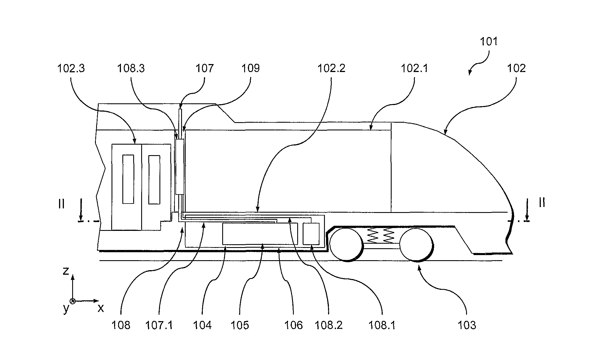
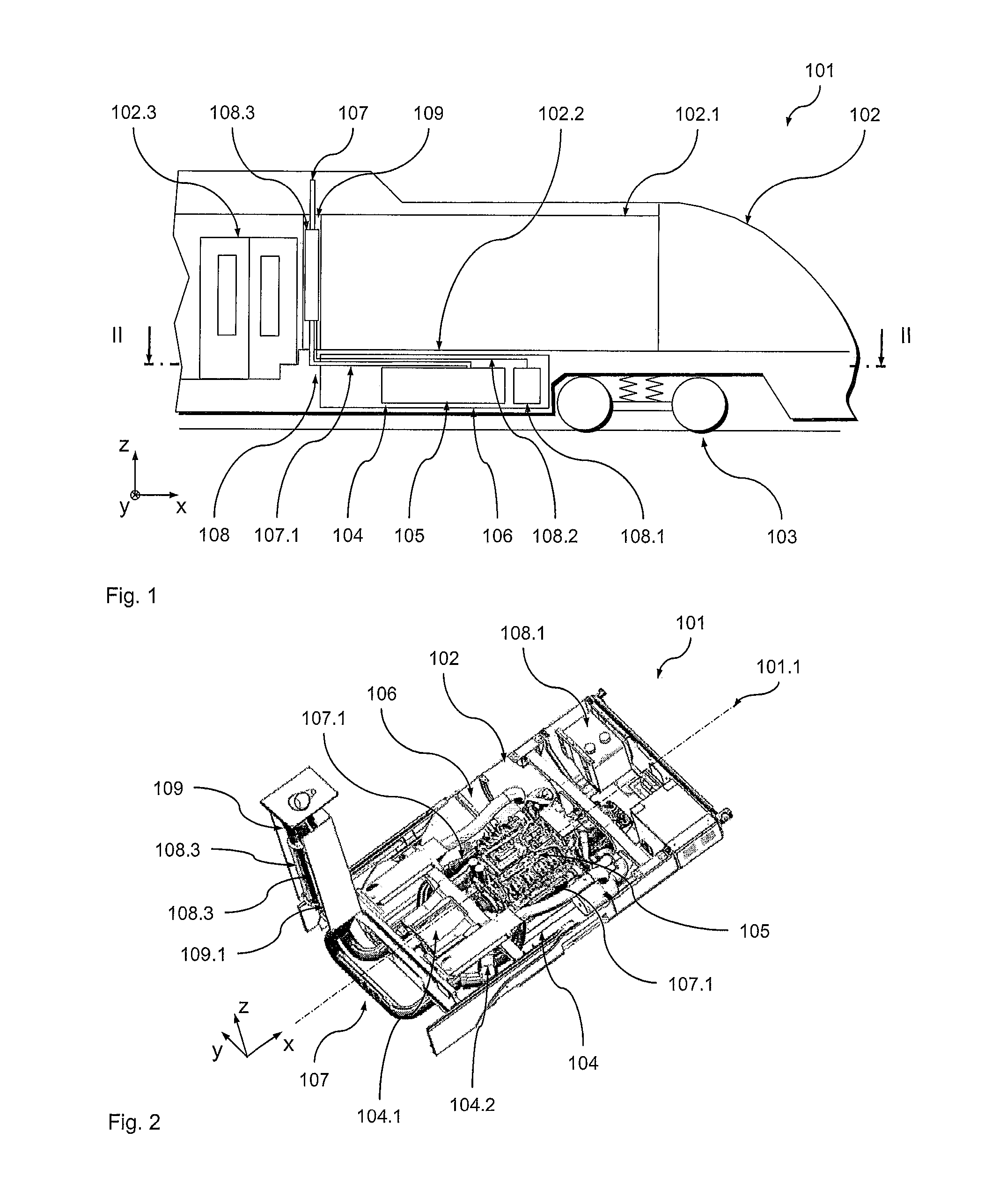
[0037]A first preferred embodiment example of the rail vehicle 101 according to the invention will be described below with reference to FIGS. 1 and 2. In order to aid in the understanding of the following explanation, FIGS. 1 and 2 show a coordinate system, wherein the x coordinate indicates the longitudinal direction of the rail vehicle 101, the y coordinate indicates the transverse direction of the rail vehicle 101 and the z coordinate indicates the height direction of the rail vehicle 101.

[0038]FIG. 1 shows a schematic lateral view of a portion of the vehicle 101, which has a longitudinal vehicle axis 101.1. The vehicle 101 comprises a vehicle body in the form of a wagon body 102 which is supported on its front end on a running gear in the form of a bogie 103. The other end (not shown in FIG. 1) of the wagon body 102 is supported on a further running gear, for example on a further bogie.

[0039]The wagon body 102 defines a vehicle interior 102.1 which is used for transporting passe...

second embodiment

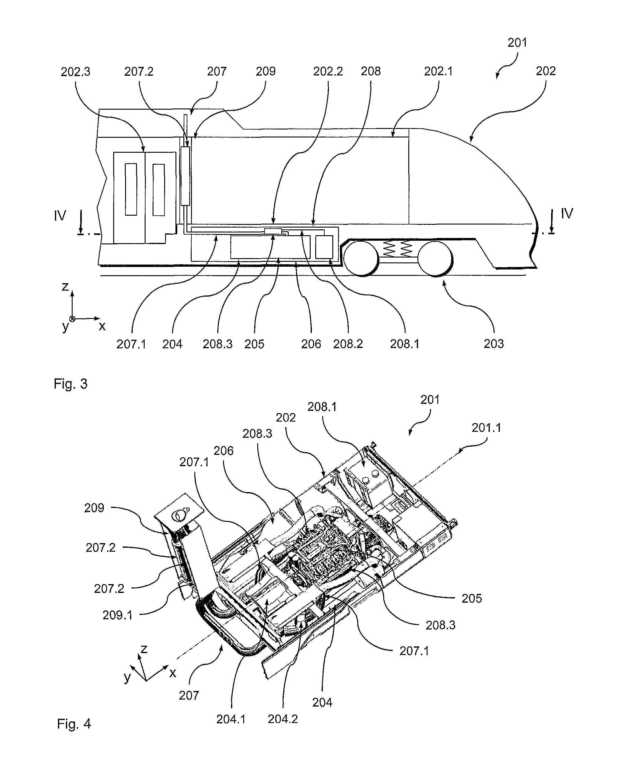
[0073]A further preferred embodiment of the rail vehicle 201 according to the invention will be described below with reference to FIGS. 3 and 4. Design and functionality of the rail vehicle 210 in principle correspond to those of rail vehicle 101 according to FIGS. 1 and 2, so that it is here mainly the differences that will be addressed. Identical or like components are identified using the same reference numerals increased by 100. Unless detailed information is given below, reference is herewith explicitly made to the explanation given above with regard to these components.

[0074]In order to aid in the understanding of the explanation given below, FIGS. 3 and 4 also show a coordinate system wherein the x coordinate indicates the longitudinal direction of the rail vehicle 201, the y coordinate indicates the transverse direction of the rail vehicle 201 and the z coordinate indicates the height direction of the rail vehicle 201.

[0075]FIG. 3 shows a schematic lateral view of a portion ...


PUM


Abstract

A rail vehicle comprising a vehicle body defining a vehicle interior, an internal combustion engine and an exhaust gas system in communication with the internal combustion engine for evacuating the exhaust gases of the internal combustion engine, wherein the exhaust gas system comprises an additive supply unit designed to supply an additive for pollutant reduction to the exhaust gas stream of the internal combustion engine, and the additive supply unit comprises a reservoir for the additive and a supply section connected thereto for supplying the additive to the exhaust gas stream. The reservoir and/or the supply section is arranged in at least one body chamber of the vehicle body, wherein the at least one body chamber is provided with sound insulation and/or thermal insulation at least in the areas adjacent to the vehicle interior and/or the environment of the vehicle, which are frequented by passengers.

Description

BACKGROUND OF THE INVENTION[0001]1. Field of the Invention[0002]The present invention relates to a rail vehicle having a vehicle body defining a vehicle interior, an internal combustion engine and an exhaust system in communication with the internal combustion engine for evacuating the exhaust gases of the internal combustion engine, said exhaust gas system comprising an additive supply unit designed to supply an additive for pollutant reduction to the exhaust gas stream of the internal combustion engine, and said additive supply unit comprising a reservoir for the additive and a supply section in communication therewith for supplying the additive to the exhaust gas stream.[0003]2. Description of the Related Art[0004]In rail vehicles which generate their drive energy by means of an internal combustion engine, the development tasks are more and more focused on the aspect of exhaust gas cleaning, not least because of the increasingly stringent regulations with regard to the emission l...

Claims


Application Information

Patent Timeline
IPC IPC(8): B61C5/00F01N13/14
CPCB61C5/04B61C17/02F01N3/2066F01N13/14F02B77/11F02B77/13Y02T10/24F01N2590/08F01N2340/04Y02A50/20Y02T10/12
Inventor WILLBRANDT, RALPHJAHN, STEFFEN
Owner BOMBARDIER TRANSPORTATION GMBH
Why Eureka
Try Eureka