Deburring cutter for deburring edges of drilled holes

a cutting edge and hole drilling technology, applied in the direction of reaming tools, boring/drilling equipment, milling equipment, etc., can solve the problems of inability to guarantee the exact diameter of the chamfer, uneven chamfer, variable, etc., to prevent additional cutting of the chamfer, prevent the effect of cutting aggressively, and effective removal

Active Publication Date: 2007-09-25
HEULE WERKZEUG
View PDF8 Cites 6 Cited by
  • Summary
  • Abstract
  • Description
  • Claims
  • Application Information

AI Technical Summary

Benefits of technology

[0015]Advantageously, the vertical first cutter can very effectively remove an unusually large burr of the edge of the drilled hole due to its particularly aggressive cutting action.
[0016]The following inclined second cutting edge advantageously guarantees that the chamfers are formed accurately, i.e., the surface and the countersink angle can be precisely maintained, independent of the wear of the cutting edges.
[0017]The control surface of the control edge located adjacent to the front region of the second cutting edge provides precise control of the cutter.
[0018]This may be explained by the observation that the control edge of the control surface contacts the chamfer after the chamfer is completed, thus preventing additional cutting of the chamfer that is no longer desired. This approach reliably limits the cutting action on the chamfer.

Problems solved by technology

In this disadvantageous arrangement, the control edge has been omitted, which could cause a variable, uneven chamfer.
When the cutter becomes dull, the exact chamfer diameter can no longer be guaranteed.

Method used


Image

  • Deburring cutter for deburring edges of drilled holes
  • Deburring cutter for deburring edges of drilled holes
  • Deburring cutter for deburring edges of drilled holes

Examples


Embodiment Construction

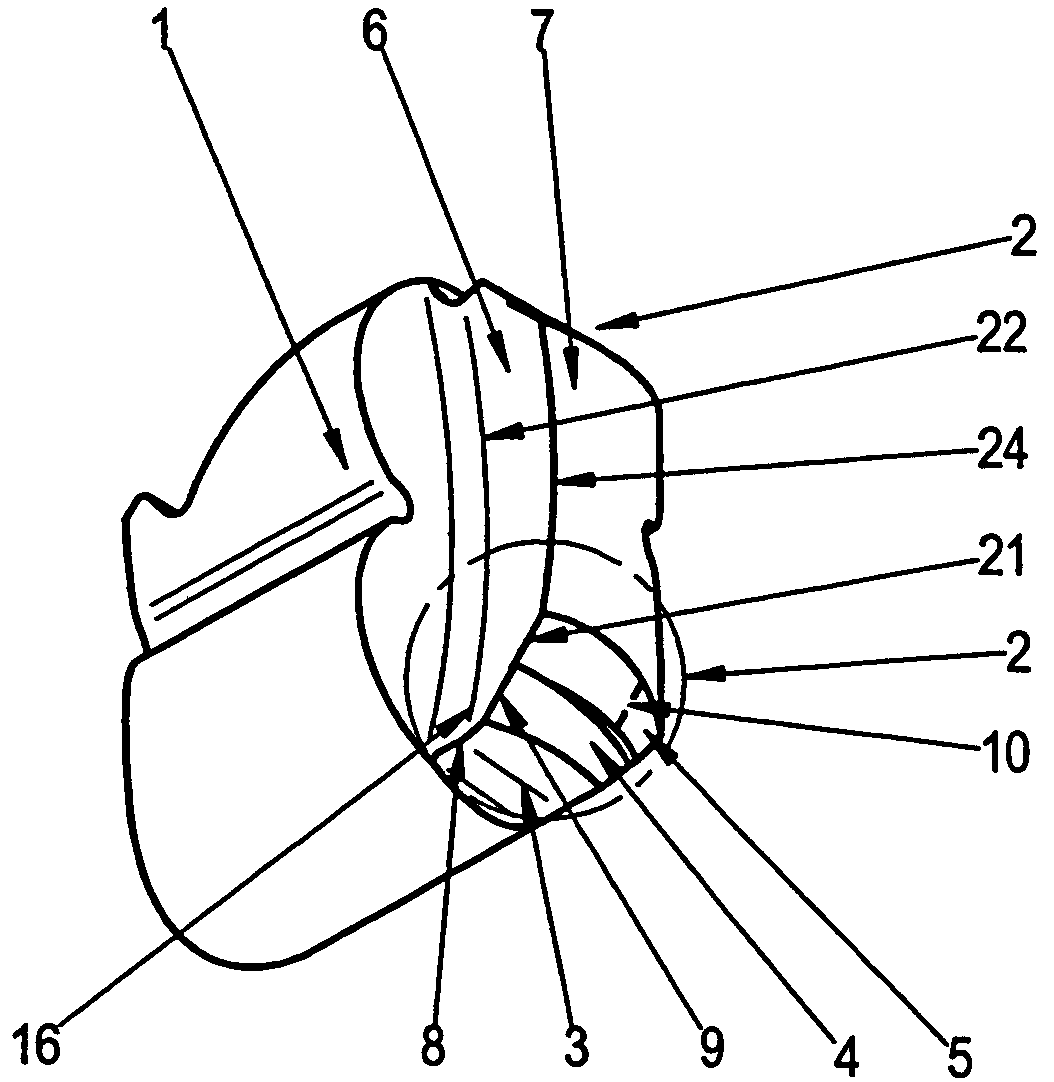
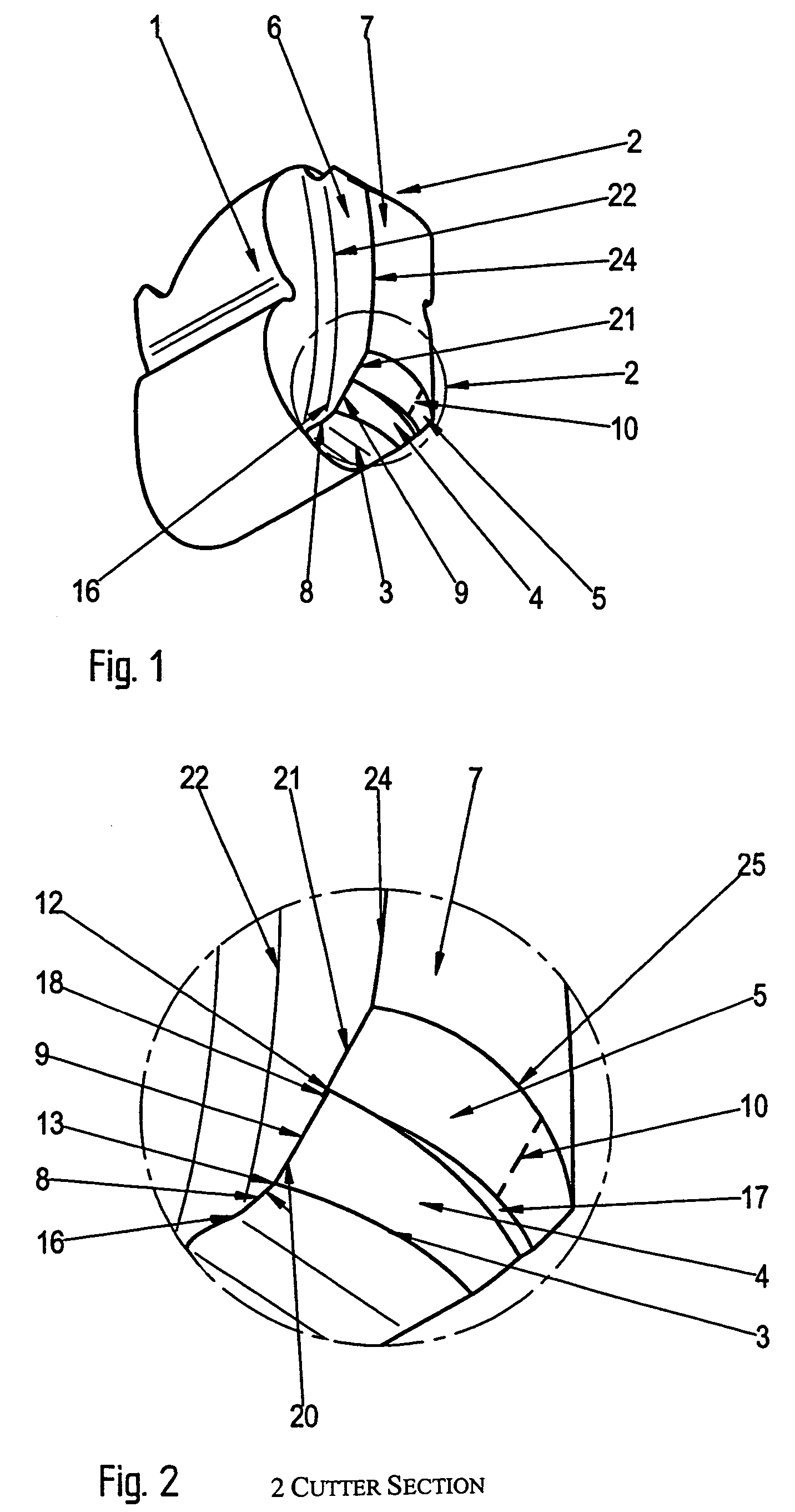
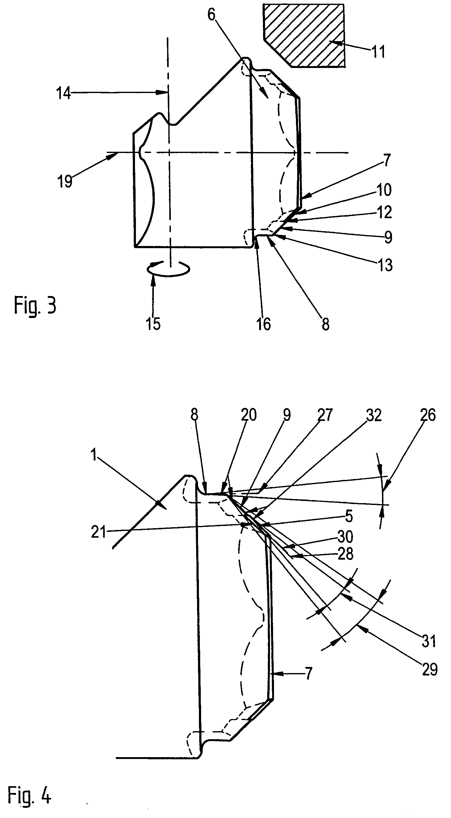
[0028]The cutter according to the invention includes cutting edges that are oriented in the forward direction (motion relative to the workpiece) and cutting edges that are oriented in the reverse direction. The cutters are hence suitable for deburring both in the forward direction and in the reverse direction. However, the invention is not limited thereto. The invention can also provide that only the cutter located on one side includes the cutting edges according to the invention, whereas the cutting edges, for example for deburring in the reverse direction, can be omitted.

[0029]The cutter 1 according to FIGS. 1 to 3 has a body that is rotatable essentially about a rotation axis 14, for example in the direction of arrow 15.

[0030]The two cutter sections for deburring in the forward and reverse direction are arranged mirror-symmetric with respect to a centerline 19.

[0031]This arrangement, however, is not required for the disclosed solution. For example, the cutter section for deburrin...


PUM

PropertyMeasurementUnit
angleaaaaaaaaaa
angleaaaaaaaaaa
angleaaaaaaaaaa

Abstract

The first cutting edge can advantageously remove a large burr from the edge of a drilled hole with high effectiveness, because of the particularly aggressive cutting action of the first cutting edge. The following inclined second cutting edge advantageously allows precise chamfers to be cut, i.e., the surface and the angle of the counter bore can be precisely maintained, independent of the wear on the cutting edges. A control surface located adjacent to the cutting edge in the forward region enables a precise control of the cutter.

Description

BACKGROUND OF THE INVENTION[0001]The invention is directed to a deburring cutter according to the preamble of claim 1.[0002]A first embodiment of a cutter, known as a DEFA cutter, by the same applicant has a straight, vertical cutting edge. A control surface is disposed on the front free end of the cutting edge. The control surface is radially inwardly inclined, does not cut, and functions only as a control surface for the vertically oriented cutting edge. The inclined control surface transitions into a horizontal front end.[0003]With the DEFA cutter, the chamfer diameter of the drilled hole to be deburred can advantageously be set very accurately and does not change during the deburring process.[0004]This may be due to the fact that the vertical cutting edge performs an excellent cutting action as a result of the forced control by the inclined control edge located subsequent to the vertical cutting edge.[0005]If the inclined control edge were omitted, the DEFA cutter would operate ...

Claims


Application Information

Patent Timeline
Patent Type & Authority Patents(United States)
IPC IPC(8): B23B51/00B23B51/10B23C5/02
CPCB23B51/101B23B51/102Y10T408/89Y10T408/905Y10T408/899Y10T408/906
Inventor HEULE, HEINRICH
Owner HEULE WERKZEUG
Why Eureka
Try Eureka