Thermal turbomachine

a technology of thermal energy and turbomachine, which is applied in the direction of liquid fuel engines, marine propulsion, and vessel construction, etc., can solve the problems of short service life of as little as a few hours, and the base material of the blades is usually somewhat unsuitable for being incorporated without protection in the coating, and achieve good wetting properties

Inactive Publication Date: 2008-09-16
ALSTOM TECH LTD
View PDF19 Cites 13 Cited by
  • Summary
  • Abstract
  • Description
  • Claims
  • Application Information

AI Technical Summary

Benefits of technology

[0014]In a second embodiment of the present invention, there is a number of first rotor blades having two layers, namely a second abrasive layer and a first abrasive layer, at the blade tip. The top abrasive layer has an aggressive cutting action but only a low thermal stability. The lower abrasive layer, which appears after the upper abrasive layer has worn away, is then less aggressive in terms of its cutting behavior but on the other hand is significantly more thermally stable.
[0016]The abrasive layers preferably consist of very hard cubic boron nitrides with a titanium coating which are embedded in a matrix of filler material. The matrix in which the particles are embedded consists of a relatively ductile material with good wetting properties. The benefit of these coatings consists in the combination of the aggressive cutting behavior produced by the hard materials and the ductility provided by the ductile matrix. The good wetting between titanium coating and compatible filler thereby results in a system which is able to withstand even the strong mechanical loads during the abrasion process. The filler used in the coating of compressor blades is either a steel alloy which is similar to the base material or a nickel material with small added amounts of Bi and S. For components from the turbine stage in which higher temperatures prevail, it is likewise possible to use suitable superalloys based on nickel or cobalt.

Problems solved by technology

It has been found that abrasive layers with very good cutting properties have only a very short service life of as little as just a few hours.
However, the base material of the blades is usually somewhat unsuitable to being incorporated without protection in the coating at the stator, since it can melt during the abrasion process and can then be deposited or rubbed onto the stator side.

Method used


Image

  • Thermal turbomachine
  • Thermal turbomachine
  • Thermal turbomachine

Examples


Embodiment Construction

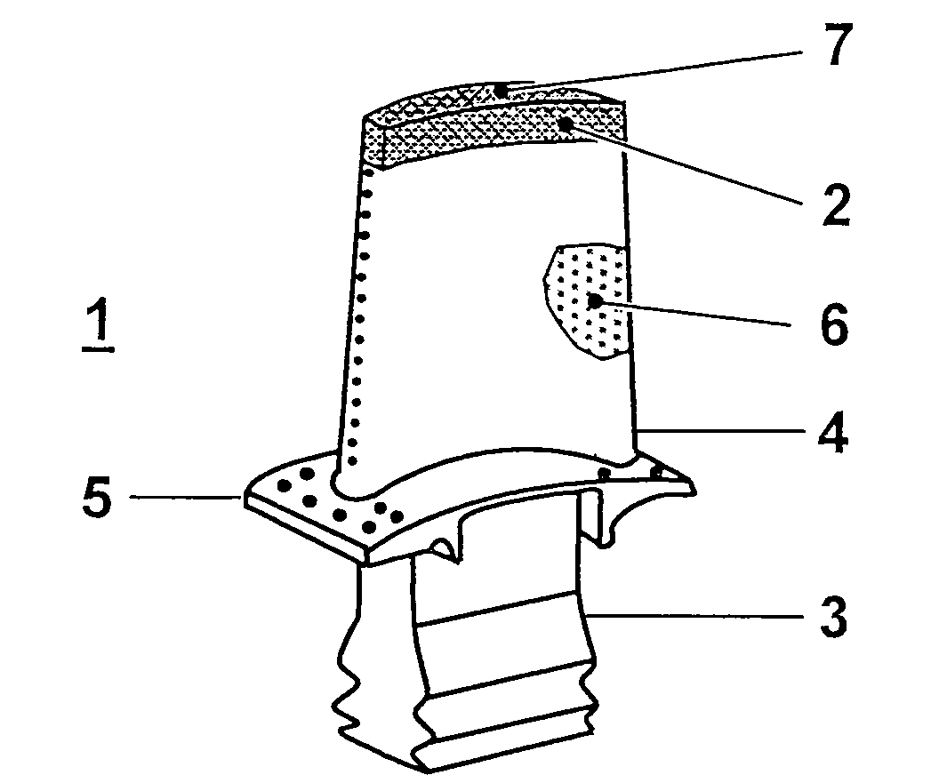
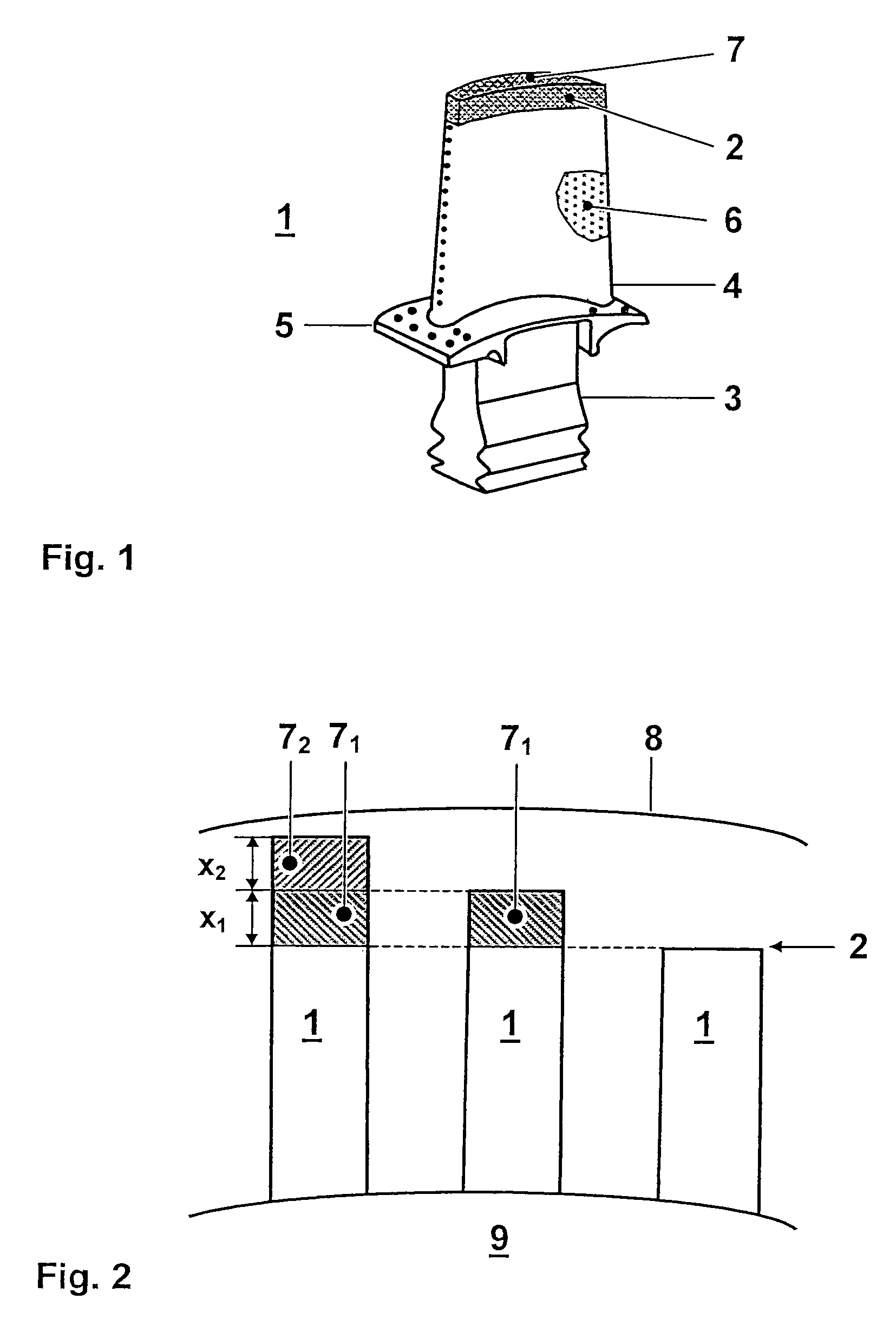
[0027]Referring now to the drawings, FIG. 1 shows a rotor blade 1 of a gas turbine, a compressor or some other thermal turbomachine. The rotor blade 1 comprises a main blade part 4 having a blade tip 2 and a blade root 3, by means of which the rotor blade 1 is mounted on a rotor 9. A platform 5, which protects the blade root 3 and therefore the rotor 9 from the fluids flowing around the main blade part 4, is usually arranged between the main blade part 4 and the blade root 3. The rotor blade 1 may be coated with a protective layer 6 of MCrAlY and additional ceramic material (TBC). An abrasive protective layer 7 is arranged at the tip of this rotor blade 1.

[0028]FIG. 2 shows an excerpt from a row of rotor blades belonging to the thermal turbomachine. The rotor blades 1 are secured to the rotor 9 and arranged opposite the stator 8. According to the invention, a small number of the rotor blades 1 belonging to a row of rotor blades arranged over the circumference of the rotor 9 are equi...


PUM


Abstract

A thermal turbomachine is disclosed having at least one row of rotor blades. At least one first rotor blade has a greater radial length than the others and at the blade tip is equipped with a first abrasive layer. At least one rotor blade which has a shorter radial length than the first rotor blade is equipped with a second abrasive layer at the blade tip. The first abrasive layer has a better cutting capacity and a lower thermal stability than the second abrasive layer. During commissioning of the thermal turbomachine, the first abrasive layer is in contact with the abradable layer of the stator, and during continuous operation of the thermal turbomachine the second abrasive layer is in contact with the abradable layer of the stator.

Description

[0001]This disclosure is based upon Swiss Application No. 2003 0674 / 03, filed Apr. 14, 2003, and International Application No. PCT / EP2004 / 050512, filed Apr. 13, 2004, the contents of which are incorporated by reference herein.BACKGROUND OF THE INVENTION[0002]1. Field of the Invention[0003]The invention is based on a thermal turbomachine having a rotor, a stator, an abradable layer located on the stator and at least one row of rotor blades which are arranged opposite the stator around the circumference of the rotor.[0004]2. Discussion of Background[0005]The guide veins and rotor blades of gas turbines or compressors are exposed to strong loads. To keep the leakage losses from the thermal turbomachine at a low level, the rotor blade of the turbomachine is matched to the stator in such a manner that a stripping action occurs. A honeycomb structure is arranged at the stator of the gas turbine or compressor, opposite the rotor blade. A compressor having a honeycomb structure of this type...

Claims


Application Information

Patent Timeline
Patent Type & Authority Patents(United States)
IPC IPC(8): F01D5/20F01D11/08F01D21/04
CPCF01D11/08F01D21/04F01D11/12
Inventor JOHNSON, NICOLAS CAMPINOHOEBEL, MATTHIASHURTER, JONASNIEDERBERGER, CHRISTOPH
Owner ALSTOM TECH LTD
Why Eureka
Try Eureka