Logical mapping for improved head switching between corresponding tracks in a data handling device

a data handling device and head switching technology, applied in the field of head switching, can solve the problems of force on the head from the disc, novel and unaccounted for devices, and limited production volume of ordinary stw technology,

Inactive Publication Date: 2007-09-25
SEAGATE TECH LLC
View PDF24 Cites 2 Cited by
  • Summary
  • Abstract
  • Description
  • Claims
  • Application Information

AI Technical Summary

Benefits of technology

[0015]In a seventh embodiment, one of the above methods also includes a step of installing onto a base pre-written discs so that a first disc contains the first track set which has a first central axis, so that a second disc contains the second track set which has a second central axis, and so that the first and second central axes are parallel and offset by several times more than a nominal track width. A crash stop is also affixed to the base so that an actuator can contact the crash stop while at least one head supported by the actuator is not over any track, and so that the actuator can move away from the crash stop so as to access one of the track sets.

Problems solved by technology

When the disc rotates, air is dragged between the rails and the disc surface causing pressure which forces the head away from the disc.
Today, ordinary STW technology is often too limited in production volume to meet increasing market demand and stringent cost reduction targets.
While promising more favorable combinations of throughput and precision, technologies like PSP and self-servowriting have caused a host of other issues that component manufacturers have yet to address.
Such devices often have novel and unaccounted-for design features such as surfaces that each have track sets that are centered about a different axis.
This typically results in a radially-dependent track incongruity between data surfaces.
Performing a headswitch between corresponding tracks on different surfaces (i.e. within a “cylinder”) is much more burdensome where such an incongruity exists.

Method used


Image

  • Logical mapping for improved head switching between corresponding tracks in a data handling device
  • Logical mapping for improved head switching between corresponding tracks in a data handling device
  • Logical mapping for improved head switching between corresponding tracks in a data handling device

Examples


Embodiment Construction

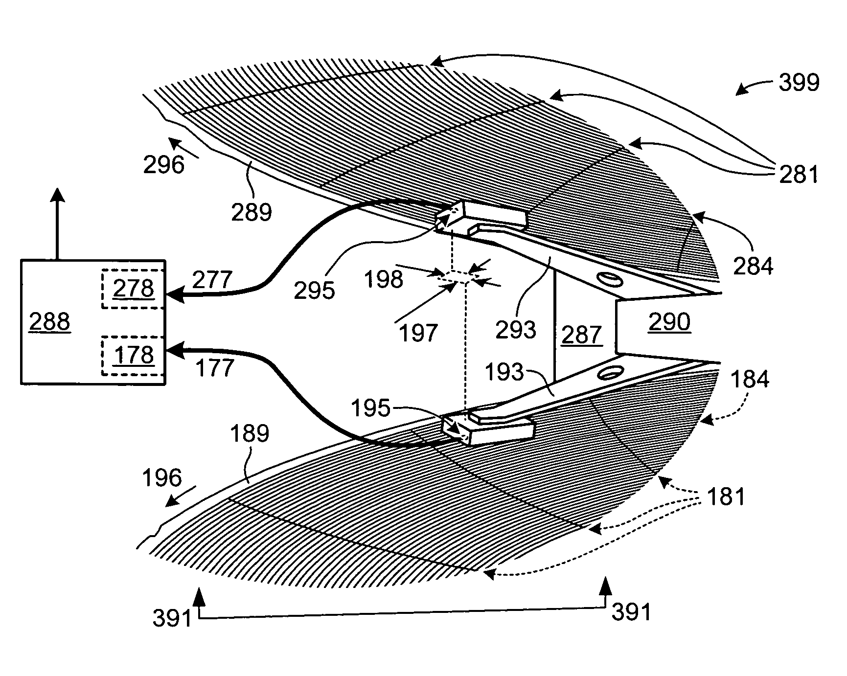
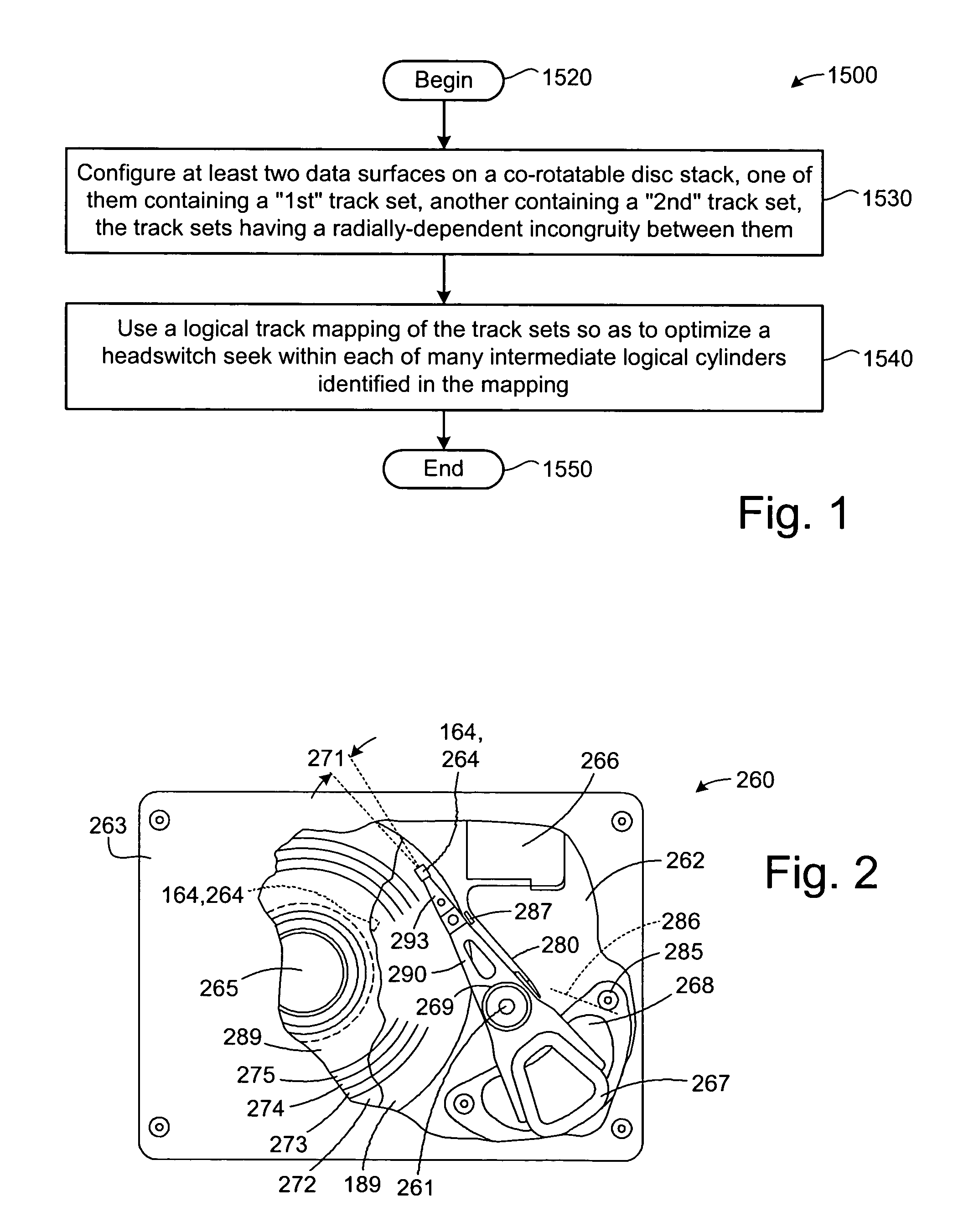
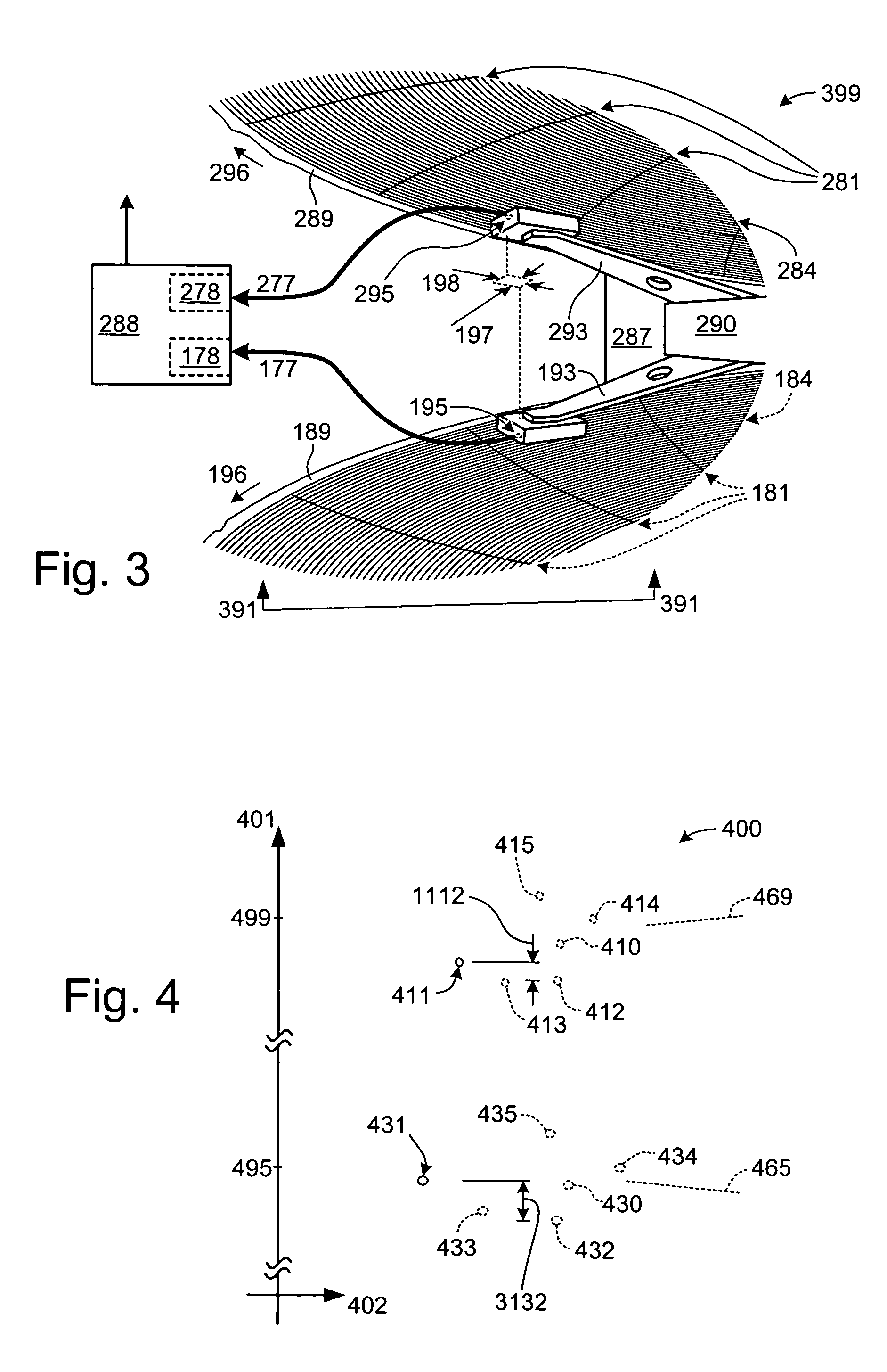
[0031]Although the examples below show more tan enough detail to allow those skilled in the art to practice embodiments of the present invention, subject matter regarded as the embodiments of the invention is broader than any single example below. The scope of the present embodiments is distinctly defined, however, in the claims at the end of this document.

[0032]To avoid needless distractions from the essence of the present embodiments, like-numbered reference numerals appearing in a later figure generally refer to the same elements as those in an earlier figure. Also, numerous aspects of basic engineering and of positioning technologies that are not a part of the present embodiments (or are well known in the art) are omitted for brevity. For example, this document does not articulate detailed and diverse methods for writing a servo sector. Neither does it include implementation decisions such as what kind of error correction codes to use or what the physical track width distributio...


PUM

PropertyMeasurementUnit
skew angleaaaaaaaaaa
rotational poweraaaaaaaaaa
pressureaaaaaaaaaa

Abstract

In a data handling system having a radially-dependent track incongruity between data surfaces, at least some tracks are logically mapped so that tracks on different data surfaces correspond with one another. The correspondence is defined by the mapping so as to shorten an average headswitch seek. For example, a logical track mapping of first and second non-coaxial track sets can be defined so as to optimize a headswitch seek within each of many intermediate logical cylinders identified in the mapping.

Description

FIELD OF THE INVENTION[0001]This application relates generally to head switching and more particularly to electromechanical data handling devices.BACKGROUND OF THE INVENTION[0002]Computers and other data handling systems have a variety of types of data storage. One common place for storing very large amounts of data inexpensively is in a disc drive. The most basic parts of a disc drive are the housing, the rotatable data storage disc(s), the actuator assembly that moves a head to various locations over each disc, and electrical circuitry that is used to transmit data to and from the disc. The disc drive also includes circuitry for encoding data so that it can be successfully retrieved and written to the disc surface. A microprocessor controls most of the operations of the disc drive as well as passing the data back to the requesting computer and taking data from a requesting computer for storing to the disc.[0003]To read and write data to the disc drive, the actuator assembly includ...

Claims


Application Information

Patent Timeline
Patent Type & Authority Patents(United States)
IPC IPC(8): G11B5/596G11B21/02G11B5/55G11B11/00
CPCG11B5/5547
Inventor WILSON, NATHANIEL BOYDWOOD, ROY LYNN
Owner SEAGATE TECH LLC
Why Eureka
Try Eureka