Method and apparatus for correlating UPS capacity to system power requirements

a technology of system power requirements and power requirements, applied in error detection/correction, redundancy hardware error correction, instruments, etc., can solve problems such as power company failure, power company failure, and malfunction, and achieve the effect of increasing the reliability of ups protected systems and reliable supply of power

Inactive Publication Date: 2007-09-25
INT BUSINESS MASCH CORP
View PDF9 Cites 14 Cited by
  • Summary
  • Abstract
  • Description
  • Claims
  • Application Information

AI Technical Summary

Benefits of technology

[0012]The principles of the present invention provide for methods and apparatuses that automatically determine the capability of UPS devices. Those principles further provide for an automatic determination if a UPS device is suitable for a particular application and can provide an automatic determination of how long a UPS device can reliably supply power. The principles of the present invention further provide for methods and apparatuses that determine which system resources are connected to which UPS device, and possibly which UPS device is connected to which AC power line. Such determinations can be used to increase the reliability of UPS protected systems by ensuring that redundant power supplies are operatively connected to different UPS devices and to different AC power lines and by ensuring that a UPS device is suitable for its intended application.
[0014]In one embodiment, a UPS device sends identifying information, such as an IP address or serial number, on an input AC power line or on a port connection (including the internet) to the protected system. The identifying information is subsequently detected by the sub-system or service processor, which then checks to ensure that redundant power supplies are not connected to the same UPS and / or to enable a controlled shutdown of system resources. The sent information also describes the power capacities of the UPS devices, which enables the protected system to determine whether a particular UPS device is suitable for its task, to signal a warning if the UPS device is not suitable, and to approximate how long each UPS device can reliably supply power. This enables a protected system to perform a controlled shut-down to mitigate damage.

Problems solved by technology

Such systems can become very large and complex, involving numerous sub-systems that are integrated together by complex interconnections.
However, no matter how reliable any power source is, it can fail.
If dual-lines are fed from different circuit breakers powered by the same power company, the power company can fail.
If different power companies are used, an electrical grid malfunction can shut-down both power companies.
Unfortunately, determining what system resource is connected to a particular UPS device and how long that device can reliably supply power becomes increasingly difficult as the number of UPS devices and system resources increase and as the protected system become more and more distributed.
Complicating the problem is the desirability of determining which system resource is ultimately connected to a particular AC power line in a dual-line system.
If that UPS fails or if the UPS device does not have sufficient capability, those sub-systems can be brought down.
However, as systems become larger and as multiple UPS devices become more common it becomes increasingly difficult to ensure that a particular UPS device is suitable for its task.
Complicating that problem is knowing what system or subsystem is actually being protected by a particular UPS device.
Wiring errors or changes to a system over time can make it difficult to determine what is actually being protected.
Determining whether a UPS device is suitable for its task is very difficult a as system expands over time, such as by adding new sub-systems, or changes over time, such as replacing an existing sub-system with a newer one.
Dual line Cord Configurations add an additional layer of complexity due to the power supplies will draw half their max load during normal operation.

Method used


Image

  • Method and apparatus for correlating UPS capacity to system power requirements
  • Method and apparatus for correlating UPS capacity to system power requirements
  • Method and apparatus for correlating UPS capacity to system power requirements

Examples


first embodiment

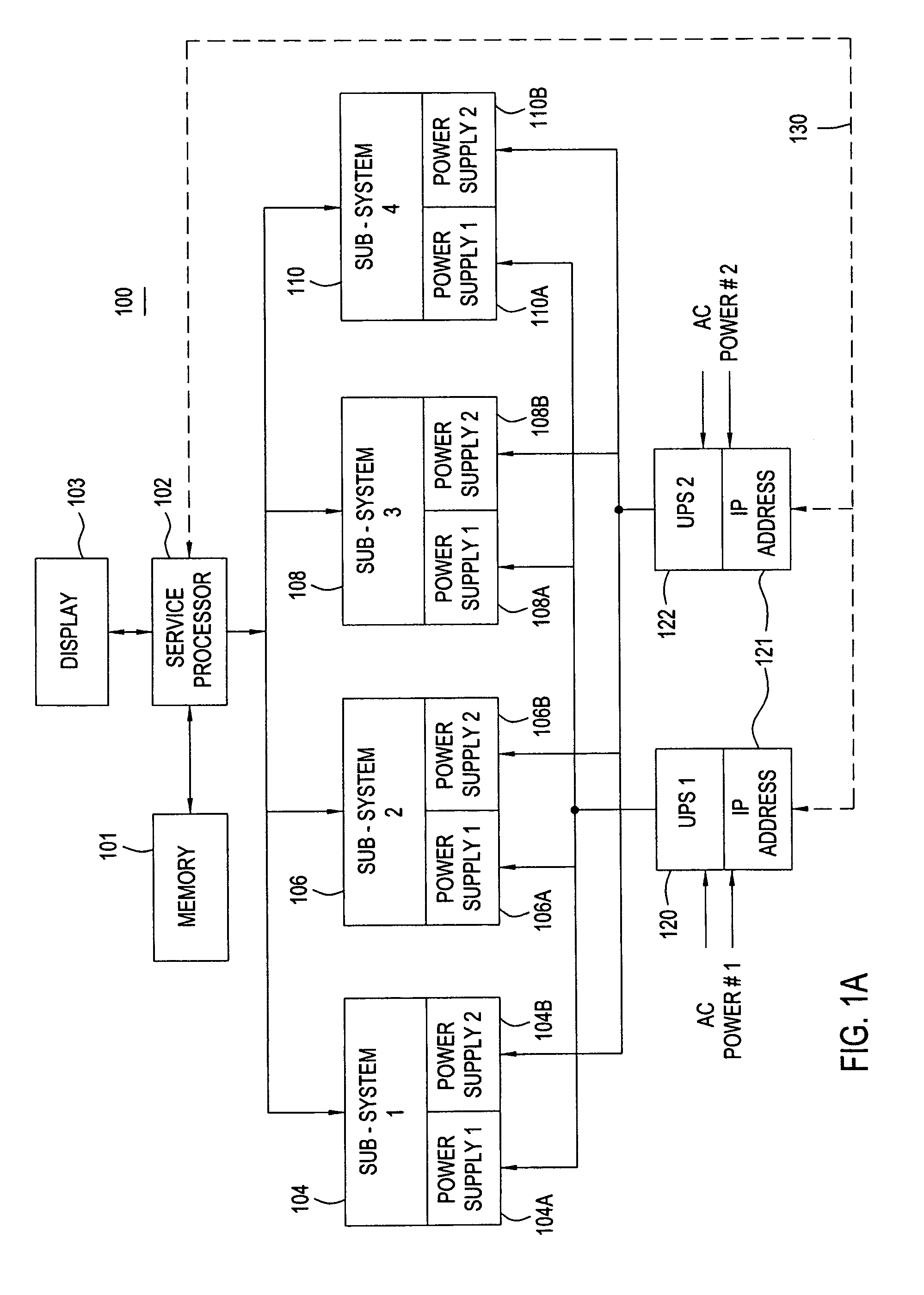
[0025]FIG. 1A is a schematic depiction of a first embodiment high reliability system 100 that is suitable for practicing the present invention. The system 100 includes numerous subsystems, each of which includes a redundant power supply. The system 100 includes a service processor 102 that controls and monitors the overall operation of the system 100. The service processor 102 is operated by software that is stored in memory 101 and that implements the overall purpose of the system 100. As the present invention relates to ensuring the integrity of the system power, part of that software, referred to herein as power micro-code, will be specifically discussed.

[0026]The system 100 includes a plurality of N (an integer) sub-systems, illustrated by the subsystems 104, 106, 108, and 110, each of which includes two power supplies, labeled 104A-104B through 110A-110B. Each power supply can individually power its associated sub-system, e.g., the power supply 106A can completely power the sub...

second embodiment

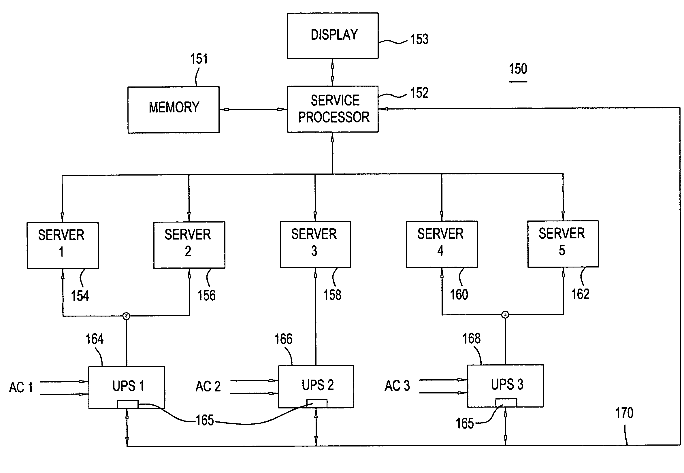
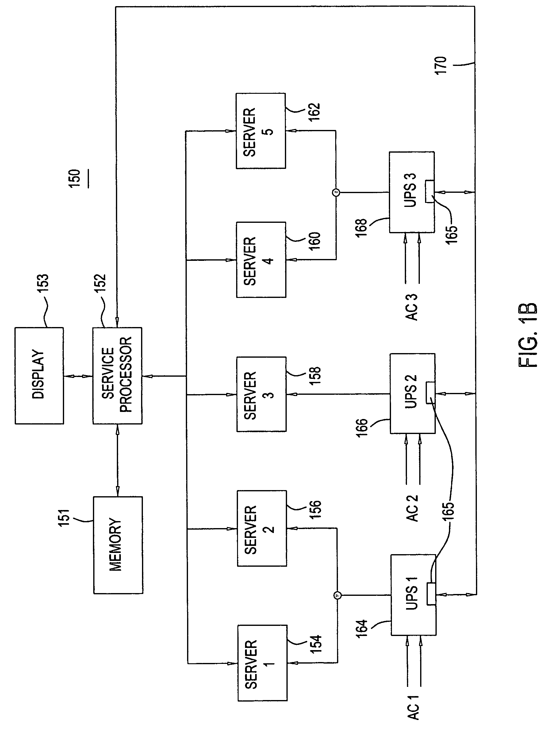
[0030]FIG. 1B is a schematic depiction of a second embodiment high reliability system 150 that is suitable for practicing the present invention. The system 150 includes a plurality of distributed subsystems which are not all connected to the same UPS system or to the AC input line. As shown, the system 150 includes a service processor 152 that controls and monitors the overall operation of the system 150. The service processor 152 is controlled by software that is stored in memory 151 and that implements the overall purpose of the system 150.

[0031]The system 150 includes a plurality of N (an integer) sub-systems that are illustrated by the servers (1-5), which are identified as server devices 154, 156, 158, 160, and 162. Each server device handles communications with a plurality of users. The server devices 154, 156, 158, 160, and 162 connect to uninterruptible power supplies UPS1, UPS2, and UPS3, which are identified as UPS devices 164, 166, and 168. The UPS device 164 receives its...


PUM


Abstract

Methods and apparatuses that automatically determine the capabilities of UPS devices. Systems automatically determine whether a UPS device is capable of protecting system resources by comparing the UPS capabilities against system requirements. Such systems can use that determination to approximate how long a UPS device can reliably supply power. Systems having multiple UPS devices can be implemented such that the connections of the UPS devices to system resources are automatically determined, the load on each UPS device can be found, the capabilities of the UPS devices can be obtained, a comparison between UPS load and UPS capabilities can made, and a warning of problems can be sent. Using UPS capability and load information a system can provide for a controlled shutdown of system resources.

Description

CROSS-REFERENCE TO RELATED APPLICATIONS[0001]This application is related to co-pending U.S. patent application Ser. No. 10 / 687,438, which was filed on Oct. 16, 2003 and is entitled “Method and Apparatus for Correlating System Resources to a Particular Line Cord,” hereby incorporated by reference in its entirety.BACKGROUND OF THE INVENTION[0002]1. Field of the Invention[0003]The present invention relates to improving the reliability of emergency power from uninterruptible power supplies.[0004]2. Description of the Related Art[0005]High reliability is often required in mission critical applications such as those that occur in medical, financial, communication, and military systems. Such systems can become very large and complex, involving numerous sub-systems that are integrated together by complex interconnections. For example, computer systems that process financial data can involve racks of hardware and can include hundreds of sub-systems, each with its own processors and power sup...

Claims


Application Information

Patent Timeline
Patent Type & Authority Patents(United States)
IPC IPC(8): G06F11/00G06F11/20
CPCG06F11/2015
Inventor EGAN, PATRICK K.ROSEDAHL, TODD J.
Owner INT BUSINESS MASCH CORP
Why Eureka
Try Eureka