Switch structure with overload protection

a technology of overload protection and switch structure, applied in the field of switches, can solve the problems of high cost and manufacturing difficulty, deterioration of the operation reliability of the safety mechanism, and complex structure, and achieve the effects of low cost, simple structure and high manufacturing efficiency

Inactive Publication Date: 2005-04-05
YU TSUNG MOU
View PDF23 Cites 14 Cited by
  • Summary
  • Abstract
  • Description
  • Claims
  • Application Information

AI Technical Summary

Benefits of technology

An object of the present invention is to provide a switch having a simple structure while capable of operation safety.
Another object of the present invention is to provide a switch of low costs while having overload protection.
A further object of the present invention is to provide a switch that is easy to manufacture.
Yet a further object of the present invention is to provide a switch that is reliable in cutting off power supply therethrough in an overload condition.
To achieve the above objects, in accordance with the present invention, there is provided a switch comprising a casing and first and second conductive blades. A conductive strip made of a material that bends when subject to a temperature rise is fixed to the first blade and has a free end. A conductive plate is arranged inside the casing and in electrical connection with the second blade and movable between an engaged position where the conductive plate engages the conductive strip to form an electrical connection between the first and second blades and a disengaged position where the conductive plate disengages from the conductive strip to electrically disconnect the second blade from the first blade. When an overload occurs, an excessive current flows through the conductive strip, causing the strip to bend from a normal operation condition to a breaking condition that separates the conductive strip from the conductive plate. A link is coupled to the conductive plate and defines an elongated slot receiving the free end of the conductive strip therein. The elongated slot allows the conductive plate to move between the engaged and disengaged positions without causing movement of the conductive strip while when the condutive strip is in the breaking condition, the link drivingly couples the conductive strip to the conductive plate for returning the conductive strip back to the normal operation condition. A leaf spring is pivoted between the casing and the conductive strip to retain the conductive strip in the breaking condition until the conductive strip is driven by the link back to the normal operation condition.

Problems solved by technology

For a power switch, overheating and burning caused by overload resulting from undesired shorting is one of the major concerns of operation safety.
Such switches, however, have complicated structures, making costs high and manufacture difficult.
Operation reliability of a safety mechanism may deteriorate due to aging of the parts thereof.
Such reliability problem often causes failure of timely cutting off power supplied to the switch when the switch is overloaded, leading to disasters.

Method used


Image

  • Switch structure with overload protection
  • Switch structure with overload protection
  • Switch structure with overload protection

Examples


Embodiment Construction

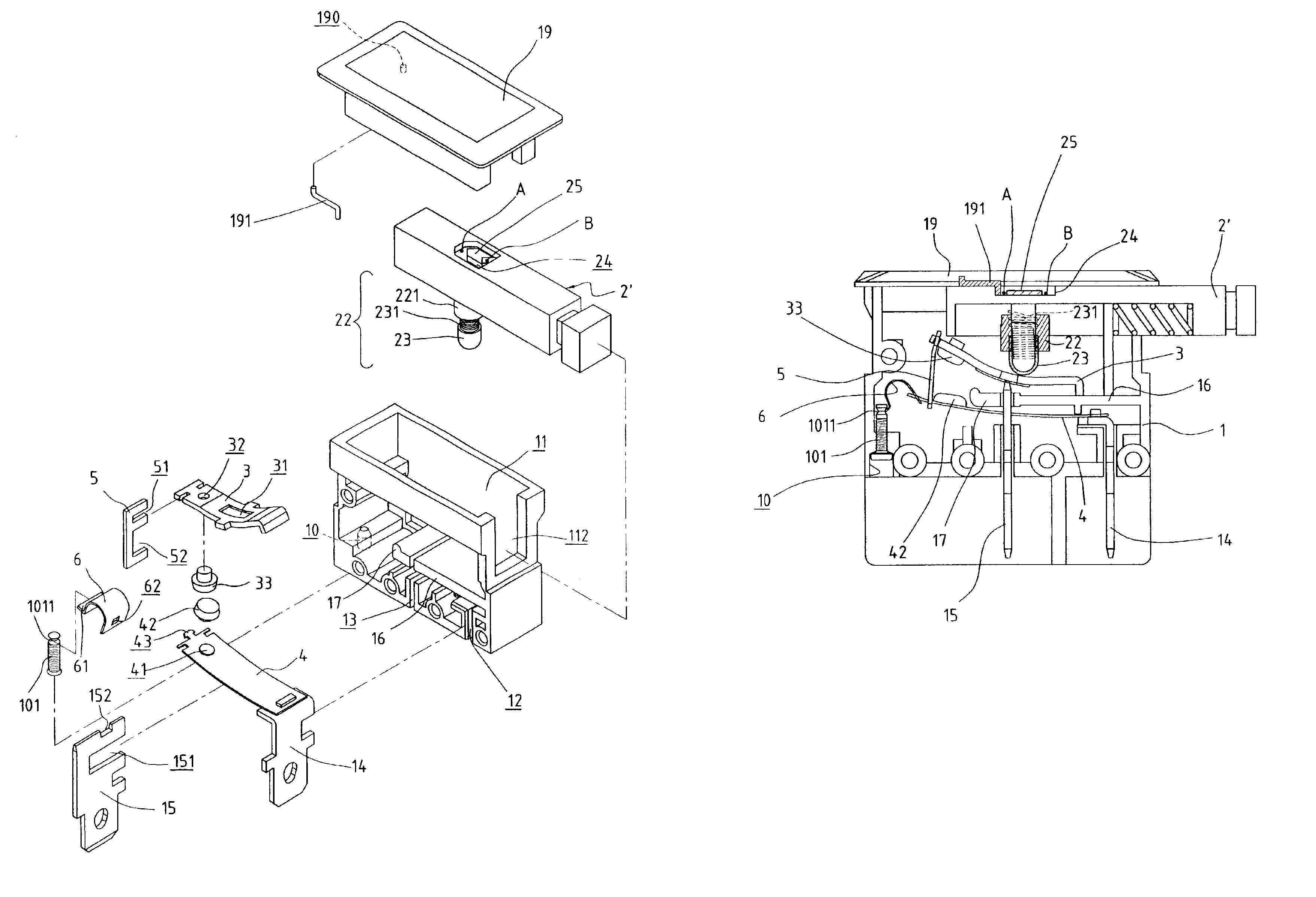
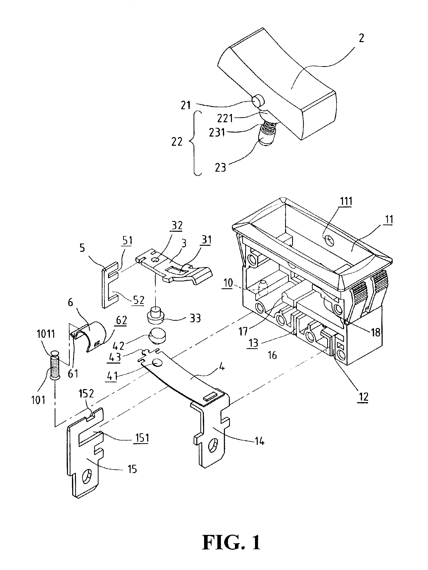
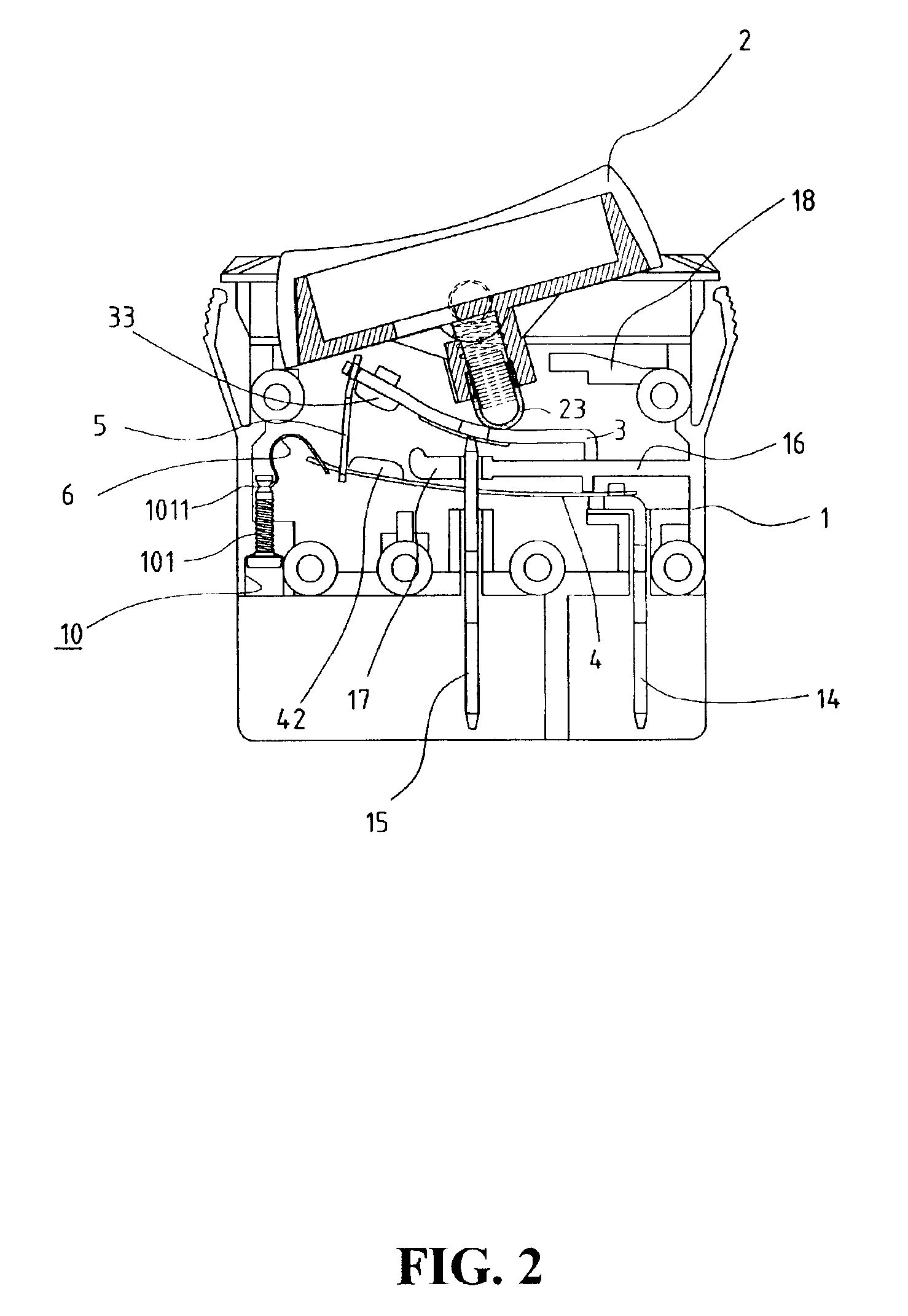
With reference to the drawings and in particular to FIGS. 1-3, a switch constructed in accordance with the present invention comprises a casing 1 forming an interior space (not labeled) and having opposite side walls (not labeled) defining a top opening 11 in communication with the interior space. Aligned holes 111 are defined in the sidewalls. A rotation button 2 is partially received in the opening 11 and has opposite pivot pins 21 rotatably received in the holes 111 of the casing 1 whereby the button 2 is rotatable between first and second positions respectively associated with ON and OFF conditions of the switch as shown in FIGS. 3 and 2.

A driver assembly 22 is formed on an underside of the button 2 and extends into the interior space of the casing 1. The driver assembly 22 comprises a cylinder 221 extending from the underside of the button 2 inside which a cap 23 is partially and movably received. A biasing element 231, such as a helical spring, is mounted between the cylinder ...


PUM


Abstract

A switch includes a casing and first and second conductive blades. A conductive strip made of a material that bends when subject to a temperature rise is fixed to the first blade and has a free end. A conductive plate is arranged inside the casing and in electrical connection with the second blade and movable between an engaged position where the conductive plate engages the conductive strip to form an electrical connection between the first and second blades and a disengaged position where the conductive plate disengages from the conductive strip to electrically disconnect the second blade from the first blade. When an overload occurs, an excessive current flows through the conductive strip, causing the strip to bend from a normal operation condition to a breaking condition that separates the conductive strip from the conductive plate. A link is coupled to the conductive plate and defines an elongated slot receiving the free end of the conductive strip therein. The elongated slot allows the conductive plate to move between the engaged and disengaged positions without causing movement of the conductive strip while when the conductive strip is in the breaking condition, the link drivingly couples the conductive strip to the conductive plate for returning the conductive strip back to the normal operation condition. A leaf spring is pivoted between the casing and the conductive strip to retain the conductive strip in the breaking condition until the conductive strip is driven by the link back to the normal operation condition.

Description

FIELD OF THE INVENTIONThe present invention relates generally to a switch, and in particular to a switch having an overload protection mechanism for operation safety.BACKGROUND OF THE INVENTIONA switch is operable between an ON (connected) state and an OFF (disconnected) state for control of power supply or electrical signal transmission. For a power switch, overheating and burning caused by overload resulting from undesired shorting is one of the major concerns of operation safety. Some switches available in the market are provided with safety mechanism that automatically cuts off power supplied therethrough in order to eliminate the potential risk of overheating and burning. Such switches, however, have complicated structures, making costs high and manufacture difficult.Another concern of the safety mechanism of the power switch is the operation reliability thereof. Operation reliability of a safety mechanism may deteriorate due to aging of the parts thereof. Such reliability prob...

Claims


Application Information

Patent Timeline
Patent Type & Authority Patents(United States)
IPC IPC(8): H01H73/26H01H73/30H01H73/00
CPCH01H73/30H01H73/26
Inventor YU, TSUNG-MOU
Owner YU TSUNG MOU
Why Eureka
Try Eureka