Particle movement-type display device and particle movement-type display apparatus
a display device and particle movement technology, applied in static indicating devices, instruments, optics, etc., can solve the problems of adverse affect of display state and inability to achieve uniform black display, and achieve bright and uniform display
- Summary
- Abstract
- Description
- Claims
- Application Information
AI Technical Summary
Benefits of technology
Problems solved by technology
Method used
Image
Examples
example 1
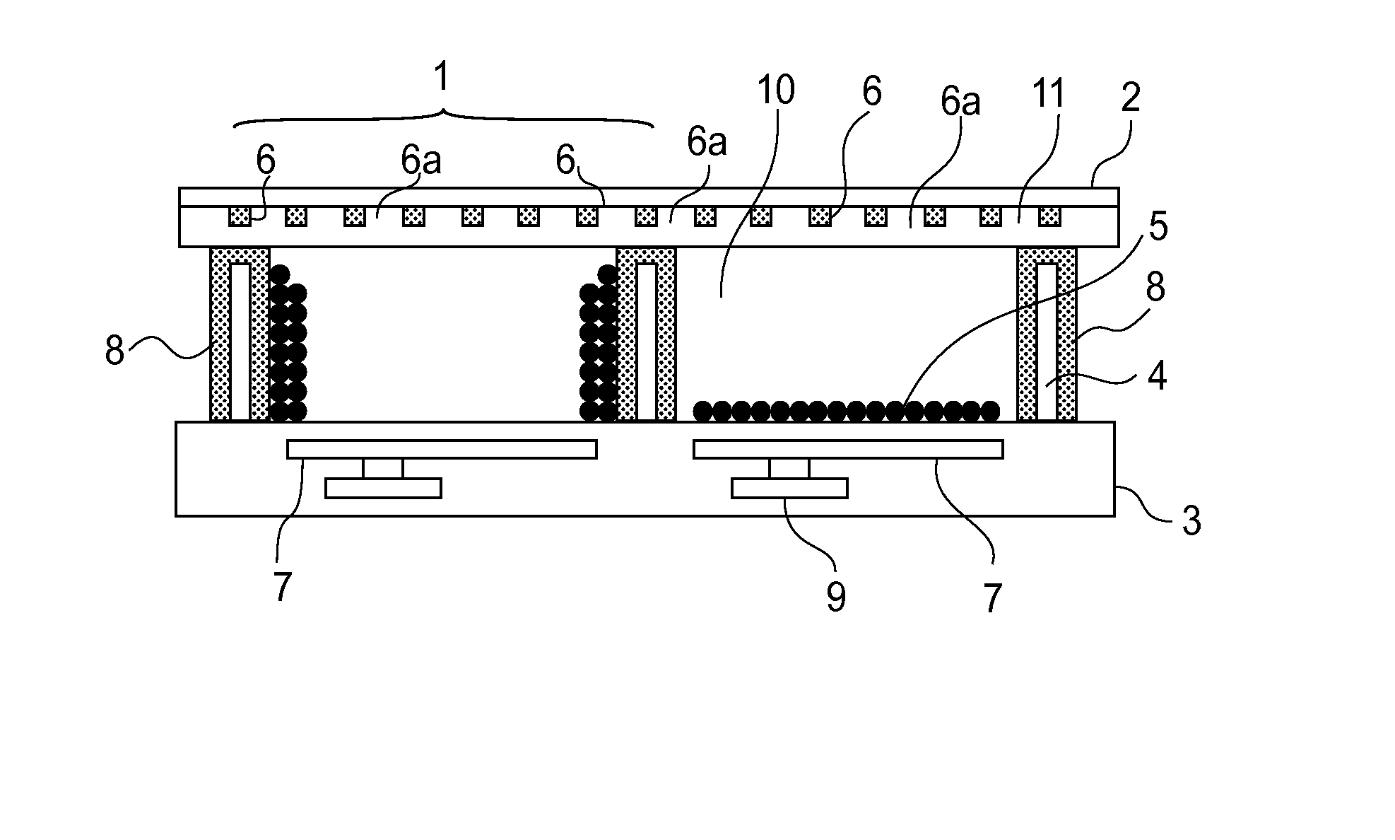
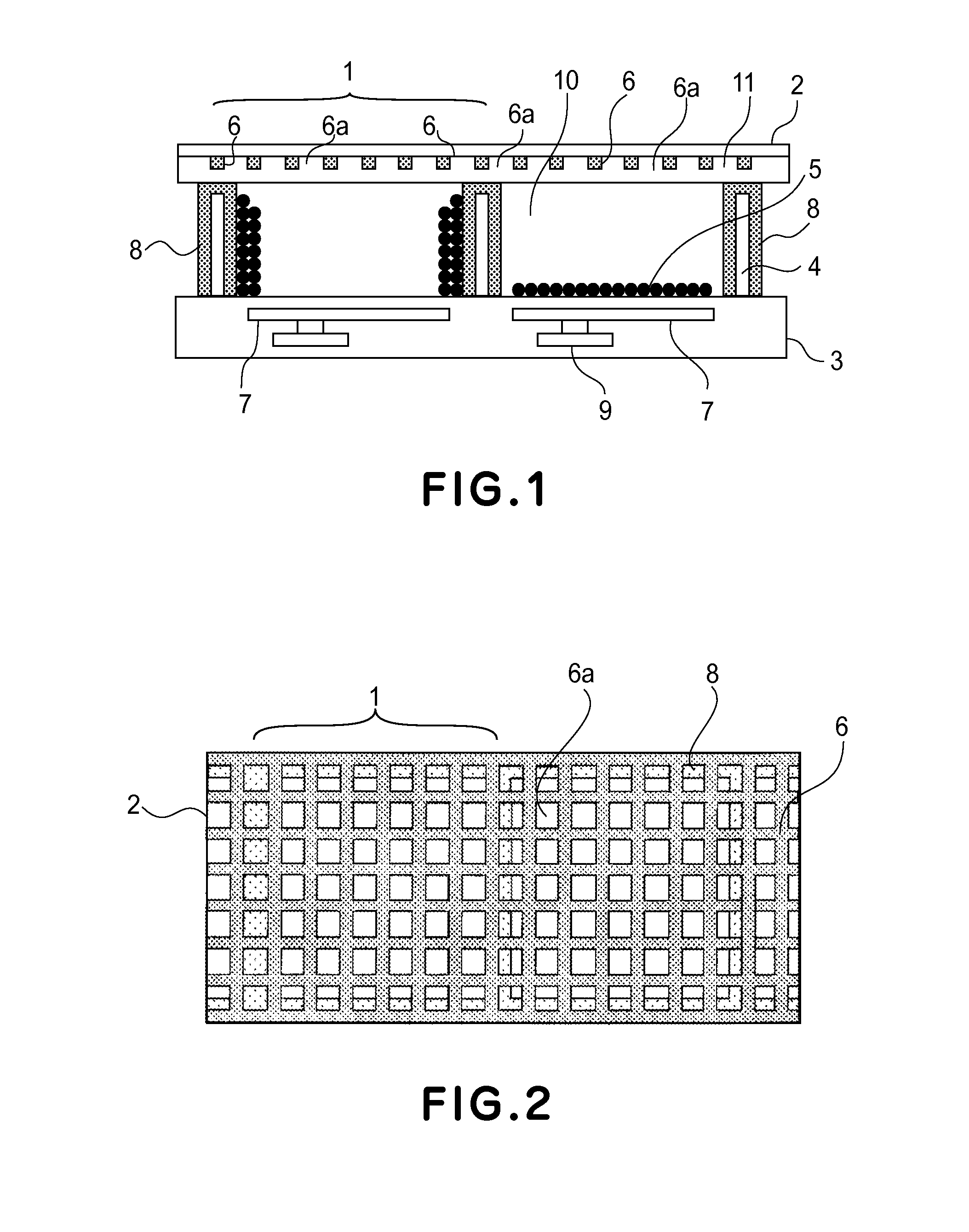
[0055]In this example, an electrophoretic display device having a structure shown in FIG. 1 was prepared in the following manner.
[0056]On a second substrate 3 formed of glass, TFT9 and wires were formed and thereon a second electrode 7 was disposed pixel by pixel through an insulating layer. The second electrode 7 was formed of aluminum and had a surface provided with a minute unevenness so as to perform reflection and scattering of incident light. Thereafter, a partition wall 4 was disposed through an insulating layer at a boundary of adjacent pixels and then a black third electrode 8 was formed at the surface of the partition wall 4. Thereafter, the third electrode 8 was coated with an insulating layer.
[0057]Next, in a space defined by the second substrate 3 and the partition wall 4, a transparent insulating liquid 10 in which charged particles 5 were dispersed was filled and thereon a first substrate 2 having a lattice-like ITO transparent electroconductive layer as a first elect...
example 2
[0059]In this example, an electrophoretic display device was prepared in the same manner as in Example 1 except that a lattice-like ITO transparent electrode layer as a first electrode 6 was formed on the surface of the first substrate 2 and was covered with a transparent resin layer 11 having a volume resistivity of about 1.0×10⁷ ohm.cm at the entire electrode surface. An electrode forming areal ratio per a pixel area of pixel was 40%.
[0060]Then, in an electrophoretic display apparatus including the thus prepared electrophoretic display device, display was effected by applying predetermined voltages to the first electrode 6, the second electrode 7, and the third electrode 8, respectively, to drive the charged particles 5. As a result, according to this example, by setting the areal ratio of the transparent electrode layer as the first electrode 6 to a pixel area of each pixel to 40%, it is possible to suppress light absorption compared with the case of forming the transparent elect...
example 3
[0061]In this example, an electrophoretic display device having a structure shown in FIG. 5(b) was prepared in the following manner.
[0062]On a second substrate 3 formed of glass, TFT9 and wires were formed and thereon a second electrode 7 formed of aluminum was disposed pixel by pixel through an insulating layer.
[0063]Next, on the second electrode 7, microcapsules 12 each comprising black charged particles 5a, white charged particles 5b, and an insulating liquid 10 were dispersed. On the surface thereon a first substrate 2 having an ITO transparent electroconductive layer as a first electrode 6 having a shape as shown in FIG. 4(a) was disposed. An electrode forming areal ratio per a pixel area of pixel was 50%.
[0064]Then, in an electrophoretic display apparatus including the thus prepared electrophoretic display device, display was effected by applying predetermined voltages to the first electrode 6, and the second electrode 7, respectively, to drive the charged particles 5. As a re...
PUM
 Abstract
Description
Claims
Application Information
 - R&D
- Intellectual Property
- Life Sciences
- Materials
- Tech Scout
- Unparalleled Data Quality
- Higher Quality Content
- 60% Fewer Hallucinations
Browse by: Latest US Patents, China's latest patents, Technical Efficacy Thesaurus, Application Domain, Technology Topic, Popular Technical Reports.
© 2025 PatSnap. All rights reserved.Legal|Privacy policy|Modern Slavery Act Transparency Statement|Sitemap|About US| Contact US: help@patsnap.com


