Handle structure

a technology of handle and handle, which is applied in the direction of wing knobs, furniture parts, manufacturing tools, etc., can solve the problems of hand pressure reaction, user discomfort when luggage devices or suitcases are heavy, etc., and achieve the effect of good grip

Active Publication Date: 2007-10-09
WU NA
View PDF19 Cites 13 Cited by
  • Summary
  • Abstract
  • Description
  • Claims
  • Application Information

AI Technical Summary

Benefits of technology

[0006]The present invention provides a handle structure which is comfortable in the hand of the user and provides the user with a good grip, in order to overcome the disadvantage of slipping off the hand of the user.
[0007]The present invention further provides a handle structure which has the better gripping feeling on the hand of the user, in order to increase the additional value and the market competition.

Problems solved by technology

The users may not feel comfortable when the luggage device or the suitcase is heavy.
Additionally, unlike handles for luggage, the comfort of the user when operating the handle has not previously been a primary consideration for the design of luggage handles.
In this regard, users sometime experience an unpleasant sensation about slipping off the hand, resulting in the pressure reaction on the hand.

Method used


Image

  • Handle structure
  • Handle structure
  • Handle structure

Examples


Embodiment Construction

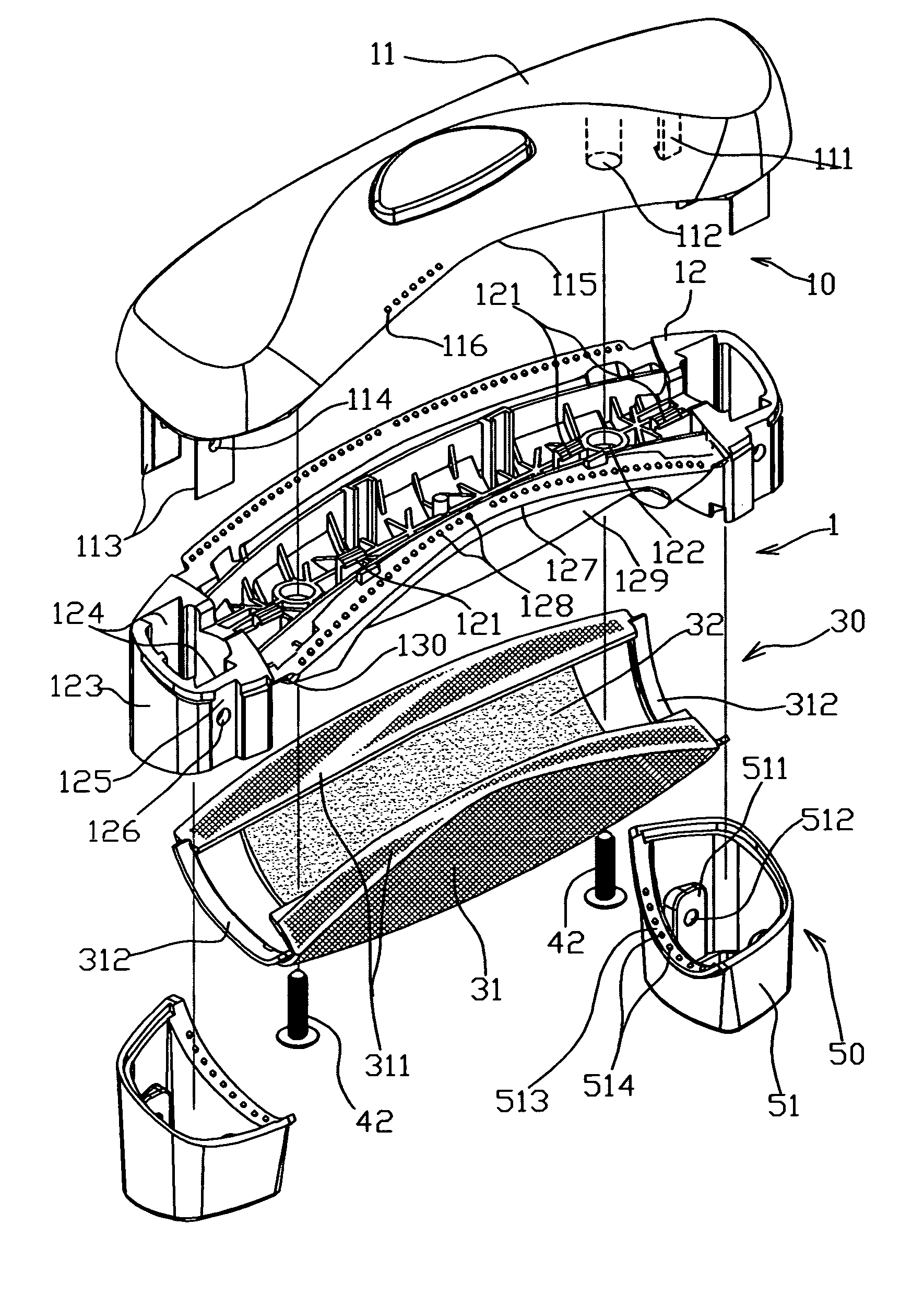
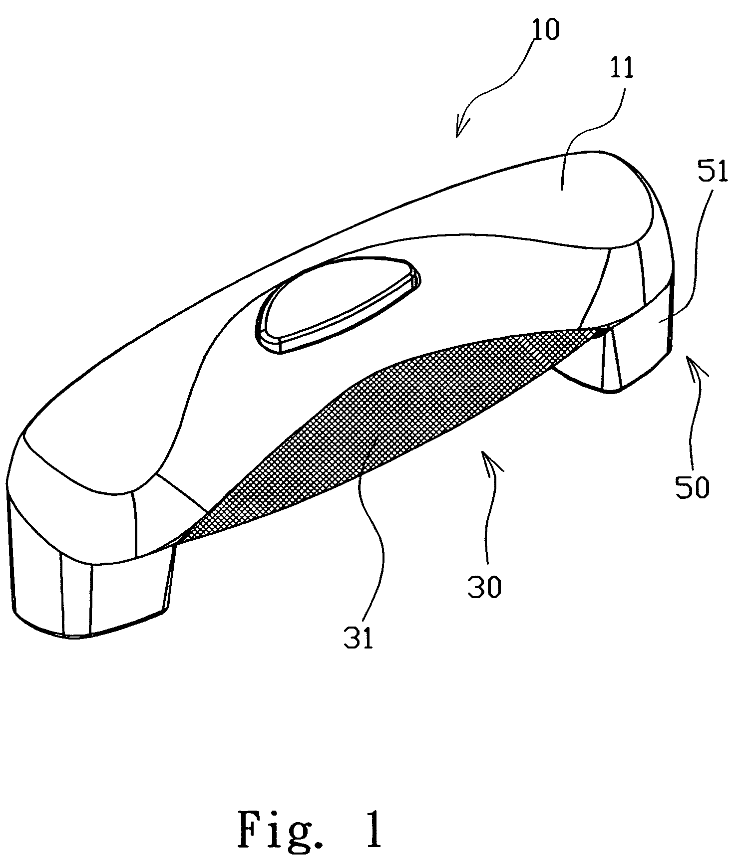
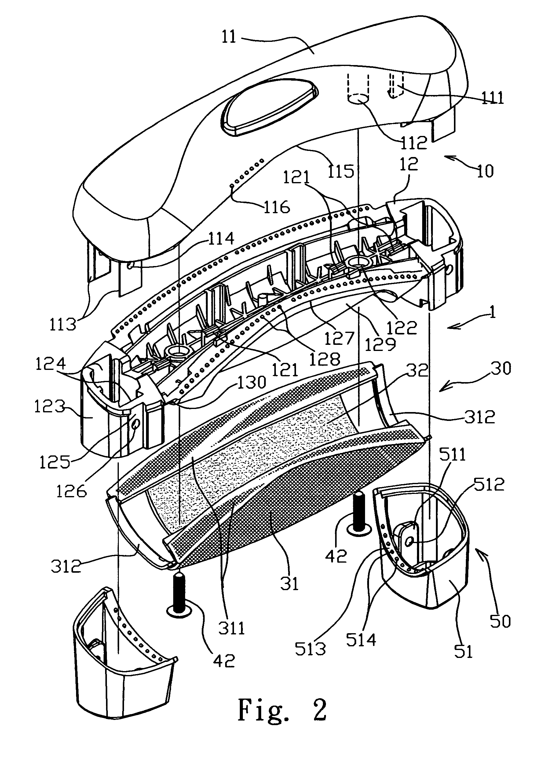
[0019]Please refer to FIGS. 1, 2 and 3, a handle structure is shown. A handle structure of the baggage illustrates the preferred embodiment of the present invention. The handle 1 comprises a main body 10, a gripping device 30 and a cover device 50. The main body 10 comprises an upper housing 11 and a lower housing 12. A plurality of hooked plates 111 and tapped holes 112 are mounted inside the upper housing 11. Two ends of the upper housing 11 extend downwardly to form two pairs of embedded plates 113. A plurality of fixed holes are mounted on the embedded plates 113. A plurality of fixed bumps 116 are disposed on two sides 115 of the gripping portion on the upper housing 11. A plurality of hooked plates 121 and tapped holes 122 are mounted inside the lower housing 12 correspondingly to the upper housing 11. Two sockets 123 are respectively formed on two ends of the lower housing 12. The socket 123 comprises an inner embedded groove 124, an outer embedded groove 125 and a through ho...


PUM


Abstract

The handle structure includes a main body and a gripping device. The gripping device is disposed on the bottom of the main body, including an outer layer and a soft member layer. The outer layer covers the soft member layer, and the soft member layer is a soft rubber, thereby providing the better gripping stability, the comfortable feeling, and the gripping quality by the soft member layer and the outer cover layer, in order to reduce the uncomfortable feeling on hand.

Description

BACKGROUND OF THE INVENTION[0001]1. Field of the Invention[0002]The present invention relates to a handle structure, and more specifically, to a handle structure which provides the better gripping stability, the comfortable feeling, and the gripping quality.[0003]2. Description of the Related Art[0004]Conventional handle for a suitcase, a vacuum cleaner, an electric fan or the like generally includes a solid portion with a leather outer sleeve. The users may not feel comfortable when the luggage device or the suitcase is heavy. Although the handle must be rigid, there is usually not a significant load-bearing requirement for handles used for suitcase. Additionally, unlike handles for luggage, the comfort of the user when operating the handle has not previously been a primary consideration for the design of luggage handles. In this regard, users sometime experience an unpleasant sensation about slipping off the hand, resulting in the pressure reaction on the hand.[0005]In view of thi...

Claims


Application Information

Patent Timeline
Patent Type & Authority Patents(United States)
IPC IPC(8): B25G1/04
CPCA45C13/26Y10T16/48Y10T16/451
Inventor WU
Owner WU NA
Why Eureka
Try Eureka