Operating apparatus for a working industrial vehicle

a technology for operating apparatuses and industrial vehicles, applied in the direction of electric propulsion mounting, battery/cell propulsion, transportation and packaging, etc., can solve the problem of inability to drive the engine by the generator motor

Inactive Publication Date: 2007-10-09
TOYOTA IND CORP
View PDF9 Cites 12 Cited by
  • Summary
  • Abstract
  • Description
  • Claims
  • Application Information

AI Technical Summary

Benefits of technology

[0012]The generator motor is set to either a generator mode in which the driving force of the engine is transmitted to the generator motor through the two-way clutch to generate power and store the power in the electricity storage means, or an electric motor mode in which the generator motor is supplied with driving power from the electricity storage means to function as an electric motor. The two-way clutch allows switching between a first state in which the transmission of driving force from the engine to the generator motor is allowed and in which the transmission of driving force from the generator motor to the engine is prevented, and a second state in which the transmission of the driving force from the generator motor to the engine is allowed and in which the transmission of the driving force from the engine to the generator motor is prevented.

Problems solved by technology

However, with the construction of the third embodiment of JP 2005-298163 A, it is impossible to drive the engine by the generator motor because the one-way clutch is then set to the disconnected state.

Method used


Image

  • Operating apparatus for a working industrial vehicle
  • Operating apparatus for a working industrial vehicle
  • Operating apparatus for a working industrial vehicle

Examples


Embodiment Construction

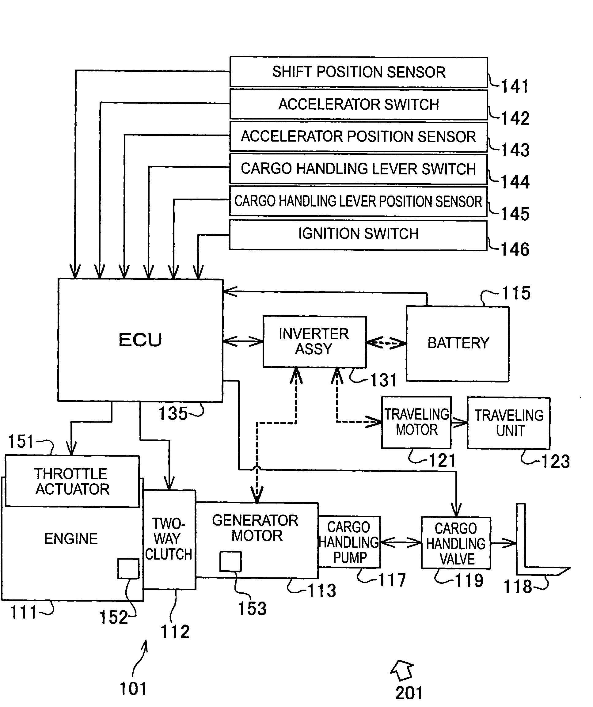
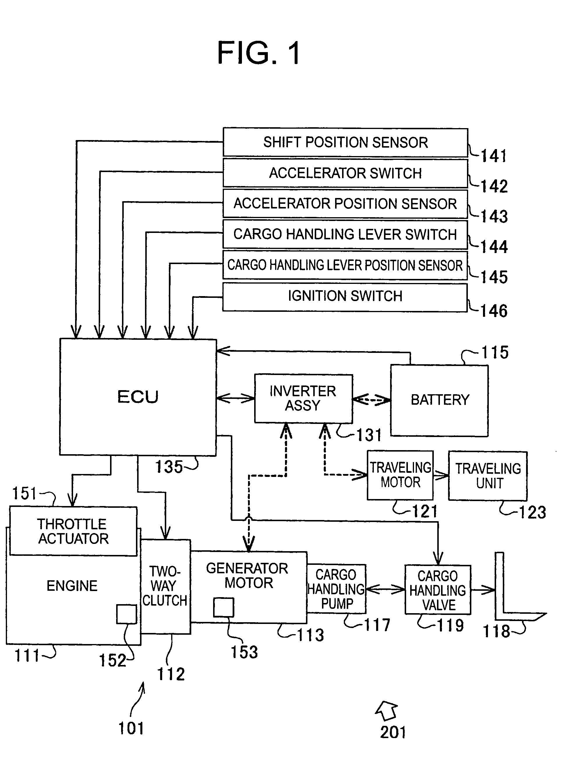
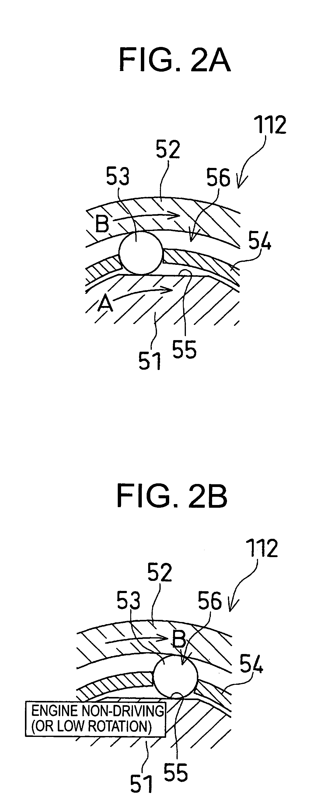
[0019]Next, an embodiment of the present invention will be described. FIG. 1 is a block diagram showing a forklift equipped with a cargo handling apparatus according to an embodiment of the present invention, FIG. 2A is a partial sectional view showing a two-way clutch in a first state, and FIG. 2B is a partial sectional view showing a the two-way clutch in a second state.

[0020]FIG. 1 shows the general construction of a cargo handling apparatus (working device) 201 of a forklift 101 as a working industrial vehicle. The cargo handling apparatus 201 is mainly composed of an engine 111, a generator motor 113, a battery (electricity storage means) 115, a cargo handling pump 117, a cargo handling valve 119, a fork 118, a traveling motor 121, a traveling unit 123, an inverter assembly 131, and an ECU (control means) 135. The cargo handling pump 117, the fork 118, and the cargo handling valve 119 form a cargo handling means (working means). In this embodiment, the cargo handling pump 117 c...


PUM


Abstract

A two-way clutch is provided between an engine and a generator motor. Further, a battery and a cargo handling pump are provided. The generator motor is set to either a generator mode or an electric motor mode. When a cargo handling load (detected by a sensor) is small, the two-way clutch is set to a first state in which transmission of driving force from the engine to the generator motor is allowed and in which transmission of driving force in reverse is prevented. Further, when the engine is stopped or idled, the cargo handling pump is driven by the generator motor in the electric motor mode. When, during the above operation, the load increases to a level above a predetermined value, an increase in output of the generator motor and an increase in engine RPM are started, and when the engine RPM becomes equal to the RPM of the generator motor, which previously increased, the two-way clutch in the first state is connected, and the cargo handling pump is driven by the engine.

Description

BACKGROUND OF THE INVENTION[0001]1. Field of the Invention[0002]The present invention relates to a so-called hybrid type operating apparatus provided in a working industrial vehicle.[0003]2. Description of the Related Art[0004]An example of a operating apparatus for an industrial vehicle of this type is disclosed in JP 2005-298163 A. According to the first embodiment of JP2005-298163A (see FIG. 1), there is disclosed a cargo handling apparatus for a cargo handling industrial vehicle having an engine, a generator motor, a clutch for connecting and disconnecting power between the engine and the generator motor, an electricity storage means, a cargo handling means (load to be driven), and a cargo handling load detecting means for detecting resistance load. The generator motor is set to either a generator mode in which a driving force of the engine is transmitted to the generator motor through the clutch to generate power and store the power in the electricity storage means, or an elect...

Claims


Application Information

Patent Timeline
Patent Type & Authority Patents(United States)
IPC IPC(8): B60K1/00B60K6/46B66F9/24B60W10/06B60W10/08B60W20/00B66F9/22
CPCB60K17/02B60L1/003B60L11/123B60W10/06B60W10/08B60W10/30B60W20/00B60K6/46B60K1/02Y10T477/23B60L2200/42B60L2270/145B60Y2200/15Y02T10/6217Y02T10/6286Y02T10/7077Y10S903/946Y02P90/60B60L50/61Y02T10/62Y02T10/70B60W2510/0208B60W10/02B60W20/15B60W2300/121Y02T10/7072
Inventor KATO, NORIHIKOICHIJO, HISASHI
Owner TOYOTA IND CORP
Why Eureka
Try Eureka