LED based light guide for dual mode aircraft formation lighting

a technology of formation lights and led light guides, applied in the field of aircraft formation lights, can solve the problems of affecting the safety of pilots, affecting the safety of aircraft,

Active Publication Date: 2007-10-09
HONEYWELL INT INC
View PDF35 Cites 11 Cited by
  • Summary
  • Abstract
  • Description
  • Claims
  • Application Information

AI Technical Summary

Benefits of technology

[0007]Exemplary embodiments of the present invention are directed to a lighting device that utilizes a diode light source, while maintaining a package thi...

Problems solved by technology

However, such conventional formation lights suffer from disadvantages relating to degradation that occurs over time.
Accordingly, formation lights utilizing EL technology quickly become hard to recognize by other pilots...

Method used


Image

  • LED based light guide for dual mode aircraft formation lighting
  • LED based light guide for dual mode aircraft formation lighting
  • LED based light guide for dual mode aircraft formation lighting

Examples


Embodiment Construction

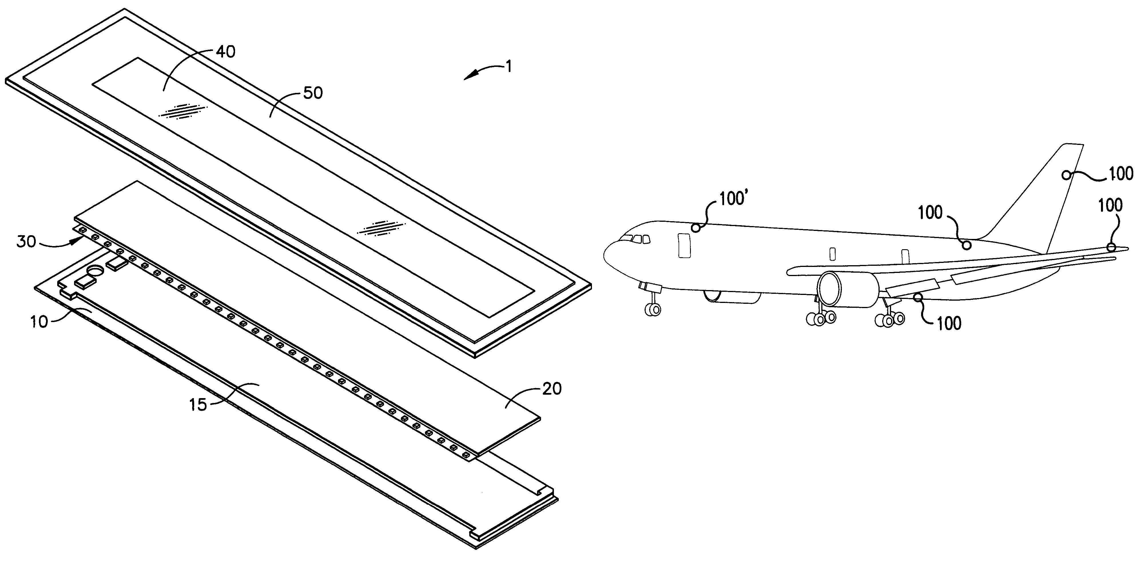
[0027]Exemplary embodiments of the present invention are directed to a lighting device that utilizes a diode light source, and is suitable for use as a formation light on the exterior of an aircraft.

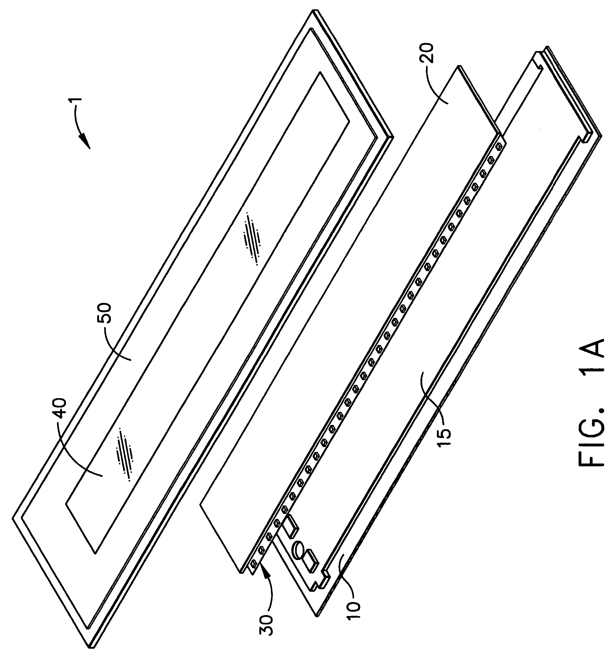
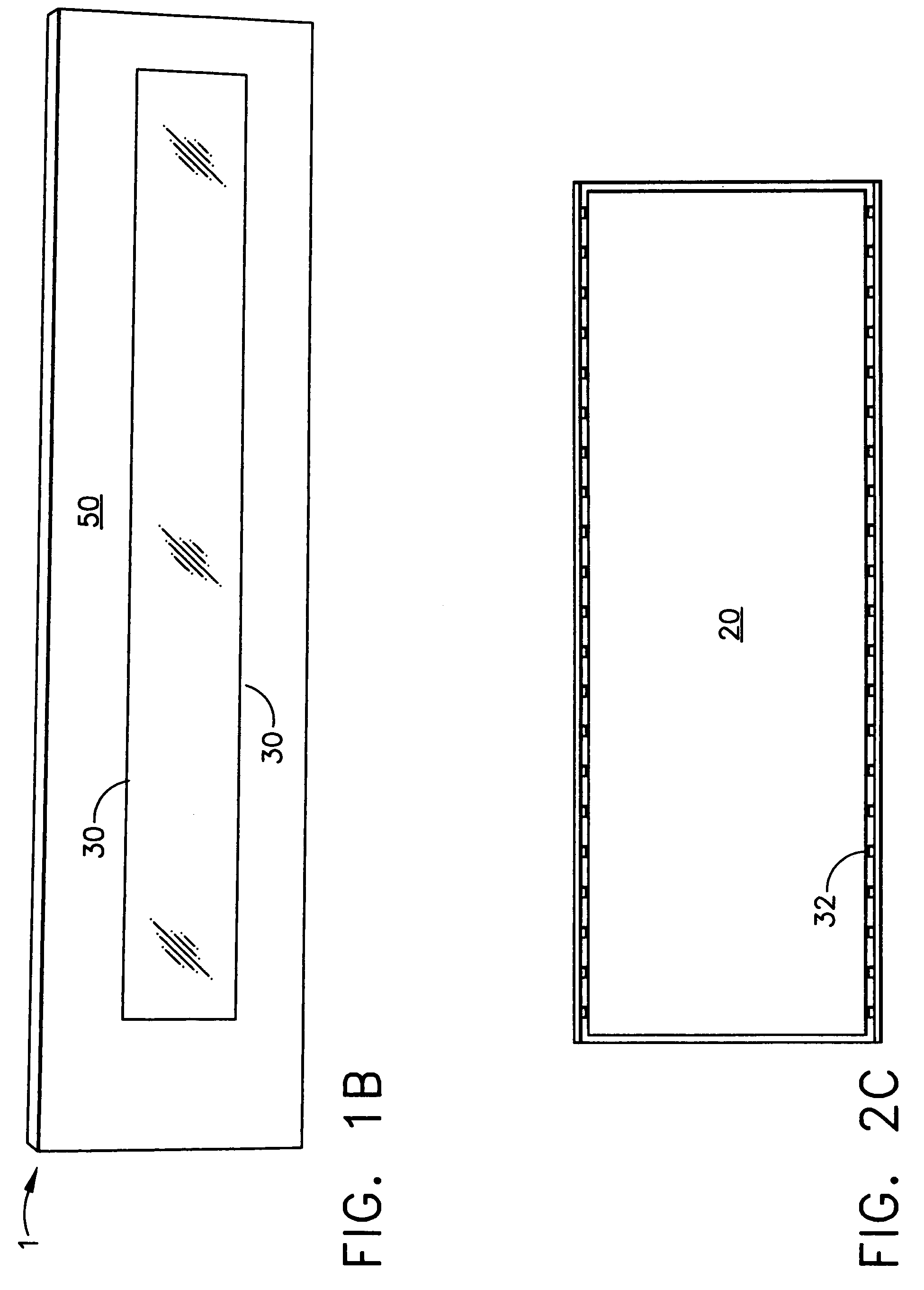
[0028]FIG. 1A illustrates various components in a lighting device according to an exemplary embodiment of the present invention. In FIG. 1A, the lighting device 1 includes a base 10 having a reflective layer or surface 15. A light guide 20 is applied over, or in front of, the base 10. A series of surface-mounted diode light sources 30 are located in relation with the light guide 20 in order to emit light in a direction incident to the peripheral edge of the light guide 20. (This may be referred to as “injecting” light into the edges of the light guide 20).

[0029]Although only one set of surface-mounted diode light sources 30 are shown, exemplary embodiment of the present invention may include two sets of diode light sources 30, each configured to inject light into a length-wise edge of th...


PUM


Abstract

A lighting device (1) includes one or more diode light sources (32), which are configured to emit light into the peripheral edges of a light guide (20). The light guide (20) includes a set of diffusing elements (22) for scattering the emitted light in a plurality of directions out of the front surface of the light guide (20). The diffusing elements (22) are distributed on the light guide (20) so that the scattered light achieves a particular characteristic, e.g., improved uniformity.

Description

CROSS REFERENCE TO RELATED APPLICATIONS[0001]This nonprovisional application claims the benefit under 35 U.S.C. § 119 of U.S. Provisional Patent Application No. 60 / 460,376 filed on Apr. 4, 2003, the entirety of which is hereby incorporated by reference.FIELD OF THE INVENTION[0002]The present invention is directed to aircraft lighting, and more particularly, to aircraft formation lights utilizing light emitting diodes (LEDs).BACKGROUND OF THE INVENTION[0003]Formation lights are mounted on the exterior of an aircraft to enhance the aircraft's visibility to other aircraft flying in close proximity. For example, many types of military aircraft utilize formation lights to provide aircraft recognition and spatial orientation during formation flight activities.[0004]Existing aircraft formation lights employ electroluminescent lamp (EL) technology, usually in the form of an electroluminescent strip. However, such conventional formation lights suffer from disadvantages relating to degradatio...

Claims


Application Information

Patent Timeline
IPC IPC(8): B64D47/02B64D47/06F21V8/00G02B6/00G02B6/25G02B6/26G02B6/32
CPCB64D47/06G02B6/0036G02B6/25G02B6/262G02B6/32B64C2027/8236G02B6/0043B64D2203/00G02B2006/0098G02B6/006G02B6/00G02B6/42
Inventor MACHI, NICOLO F.MANGUM, SCOTT R.SINGER, JEFFREY M.FERGUSON, JOSEPH L.
Owner HONEYWELL INT INC
Why Eureka
Try Eureka