EC motor and method for operating same

a technology of ec motors and motors, applied in the direction of electronic commutators, motor/generator/converter stoppers, dynamo-electric converter control, etc., can solve the problems of measurement signals, large manufacturing outlay, positioning errors when positioning hall sensors, etc., and achieve precise commutation of winding currents, simple and cost-effective manufacturing

Inactive Publication Date: 2007-10-09
SCHAEFFLER TECH AG & CO KG
View PDF20 Cites 8 Cited by
  • Summary
  • Abstract
  • Description
  • Claims
  • Application Information

AI Technical Summary

Benefits of technology

[0005]An object of the present invention is to provide an EC motor of the type mentioned at the outset that will be able to be manufactured simply and cost-effectively. An alternate or additional object of the present invention is to provide an EC motor that permits a very precise commutation of its winding currents. A further alternate or additional object of the present invention is to provide a method for operating such an EC motor.

Problems solved by technology

In particular, when the motor and the Hall sensors are purchased from different manufacturers, positioning errors can occur when positioning the Hall sensors on the stator.
This can lead to the measurement signal from several, many, or all of the Hall sensors deviating from the actual position of the rotor relative to the phase assigned to the Hall sensor.
However, this entails a considerable outlay for manufacturing.
It is also disadvantageous that the EC motor must be designed in such a way that the Hall sensors are still movable relatively to the stator at the end of the production lines.

Method used


Image

  • EC motor and method for operating same
  • EC motor and method for operating same
  • EC motor and method for operating same

Examples


Embodiment Construction

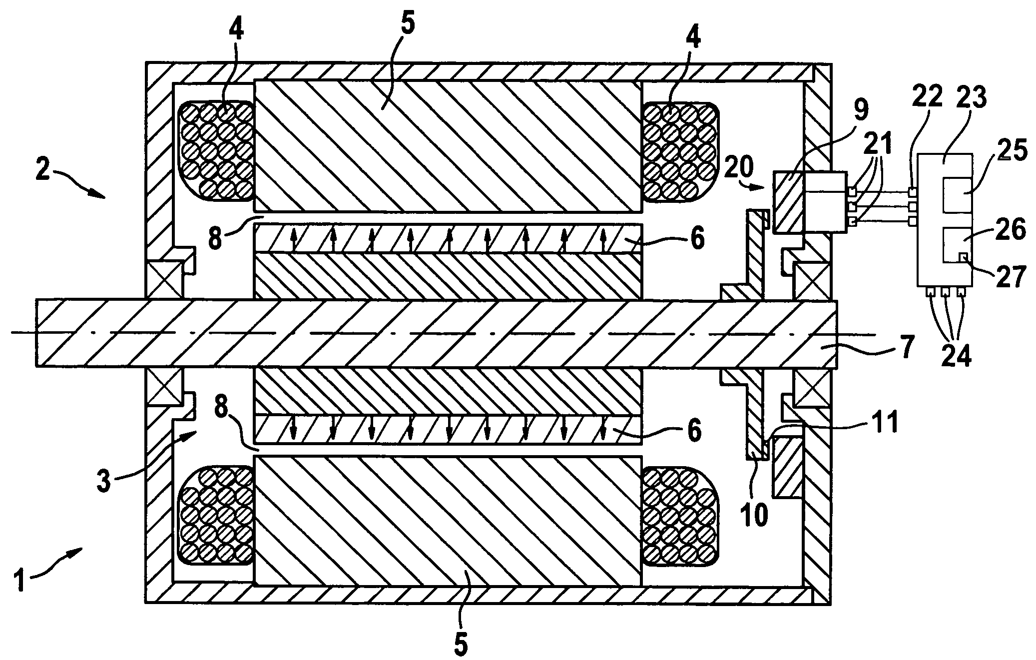
[0039]An EC motor denoted as a whole by 1 in FIGS. 4 and 5 has a stator 2 and, rotationally supported relatively thereto, an armature 3 designed as a rotor. Stator 2 has a polyphase winding 4, which passes through slots of a soft magnetic core 5 (laminated stator body). On its periphery, armature 3 has a plurality of permanent-magnetic poles 6, which are offset from one another in the relative motion direction and which are connected via a more or less cylindrical, soft magnetic carrier to a shaft 7. This shaft is rotationally supported by rolling-contact bearings on stator 2. Between soft magnetic core 5 of stator 2 and poles 6, an air gap 8 is formed, which is permeated by a magnetic field.

[0040]To record the position of poles 6 in relation to the phases of winding 4, EC motor 1 has a position-measuring device 20 which has a sensor element 9 that is hardwired to stator 2, and an encoder 10 that cooperates with the sensor element and is hardwired to armature 3 and is made of an ele...


PUM


Abstract

In a method for operating an EC motor, position-measurement signals are recorded by a position-measuring device, and, on the basis of the position-measurement signals, commutation instants are determined, at which the current supply to the EC motor is commutated. At least one correction value for at least one position-measurement error contained in the position-measurement signals is ascertained and stored. To compensate for the at least one position-measurement error, the correction value is considered when determining the commutation instants.

Description

[0001]Priority is claimed to German Application No. DE 103 50 566.0, filed on Oct. 30, 2003, the entire disclosure of which is incorporated by reference herein.[0002]The present invention is directed to a method for operating an EC (electronically commutated) motor, position-measurement signals being recorded by a position-measuring device, on the basis of the position-measurement signals, commutation instants being determined, the current supply to the EC motor being commutated at the commutation instants. The present invention is also directed to an EC motor having a stator having a polyphase winding, an armature movable relatively thereto having permanent-magnetic poles, and a position-measuring device for recording the position of the poles in relation to the phases of the winding, the position-measuring device having at least one measurement-signal output which is linked to at least one measurement-signal input of a driving device to electronically commutate the EC motor, the d...

Claims


Application Information

Patent Timeline
Patent Type & Authority Patents(United States)
IPC IPC(8): H02P6/00H02P6/12H02P6/14H02K29/08H02P6/16H02P6/18
CPCH02K29/08H02P6/12H02P6/182H02P6/16H02P6/142H02P6/15
Inventor HILL, WOLFGANG
Owner SCHAEFFLER TECH AG & CO KG
Why Eureka
Try Eureka