Commutation control method of electric steering engine driving device

A technology of electric steering gear and driving device, which is applied in the direction of electronic commutator, etc., can solve the problems that the square wave air gap magnetic field cannot be better used, the output of the brushless DC motor is not large, and the torque stability is general, etc., to achieve Simple and reliable assembly, elimination of misjudgment and wrong commutation, and high accuracy of position information

Inactive Publication Date: 2018-02-02
NANJING UNIV OF SCI & TECH
View PDF3 Cites 3 Cited by
  • Summary
  • Abstract
  • Description
  • Claims
  • Application Information

AI Technical Summary

Problems solved by technology

The currently commonly used three-three conduction commutation method cannot make good use of the flat-top part of the square-wave air-gap magnetic field. The output of the brushless DC motor is not large, and the torque stability is average. It is difficult to apply to low-speed and torque characteristics. High electric steering gear drive

Method used


Image

  • Commutation control method of electric steering engine driving device
  • Commutation control method of electric steering engine driving device
  • Commutation control method of electric steering engine driving device

Examples


Embodiment 1

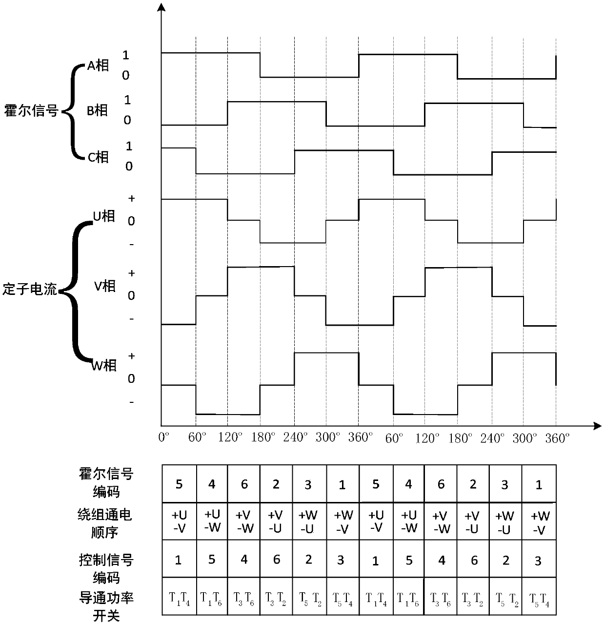
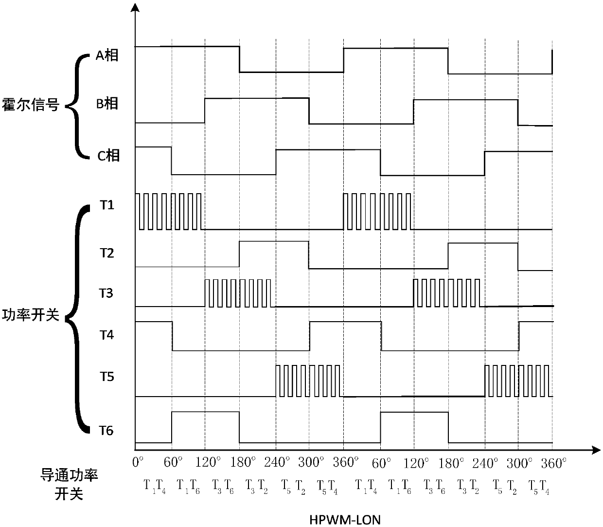
[0033] A two-to-two conduction commutation control method for an electric steering gear driving device according to the present invention includes an STM32 controller and its driver, and a three-phase Hall sensor. Wherein, the steps of the two-two conduction commutation control method are as follows:

[0034] Step 1. Use the three-phase Hall sensor installed on the brushless DC motor in a 120-degree installation method to detect the rotor position signals of the HALLA, HALLB, and HALLC three-phase brushless DC motors;

[0035] It is necessary to perform 5V voltage pull-up processing on the rotor information detected by the Hall sensor of each phase, and perform hardware filtering, so that the high-level signal of the externally collected analog square wave signal can at least reach the voltage range of 0 to 3.3V recognized by the STM32 controller Inside.

[0036] Step 2: Input the three-phase Hall analog signals of HALLA, HALLB, and HALLC to the STM32 controller, and internal...


PUM


Abstract

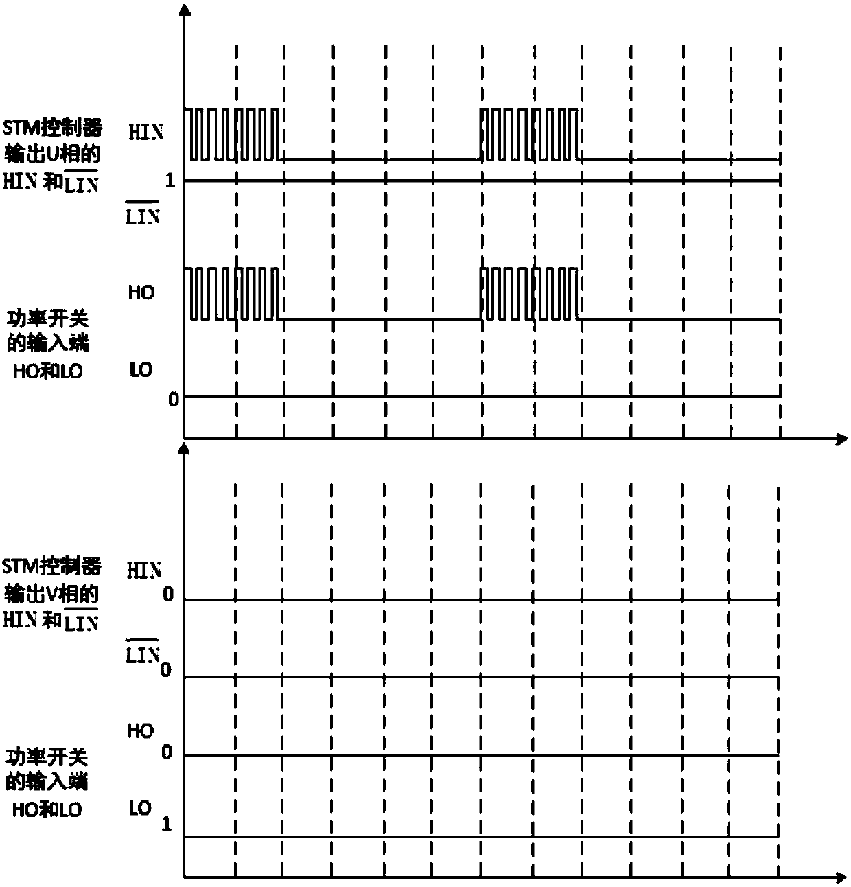
The invention discloses a commutation control method of an electric steering engine driving device. The method is used for two-two conduction commutation of a three-phase brushless direct current motor. The method comprises the following steps of using a three-phase Hall sensor installed on the brushless direct current motor to detect a rotor position signal of the three-phase brushless direct current motor; inputting a three-phase Hall simulation signal into a controller and converting into a Hall digital signal, then generating six kinds of codes and forming a six-step commutation sequence;and carrying out logic selection and determination in the controller, calculating and acquiring a three-phase UVW control signal code of a three-phase brushless direct current motor driver, through anIO port of the controller, simulating and outputting a control signal to the driver so as to carry out current commutation, and conducting two channels in three channels of UVW, wherein the two channels are power switches of an upper bridge arm and a lower bridge arm and are opened simultaneously, and other power switches are closed. The method possesses advantages that a control algorithm is simple; control driving integration is achieved; and a driving device is simple and so on. A rotor position and speed information can be accurately monitored.

Description

technical field [0001] The invention relates to the technical field of digital signal control, in particular to a phase commutation control method of an electric steering gear drive device. Background technique [0002] Compared with brushed DC motors, brushless DC motors use electronic devices instead of brushes, and use stator permanent magnets to generate the rotor magnetic field, which retains the speed regulation range of brushed DC motors to a certain extent. It has the advantages of wide range, simple control, etc., and has the advantages of low commutation loss and excellent dynamic speed regulation performance. [0003] The rotation and commutation control methods of the brushless DC motor of the actuator in the electric steering gear drive mainly include non-inductive BLDC rotor position detection and sensory BLDC rotor position detection. Among them, the sensorless BLDC rotor position detection is applied in the electric steering gear drive device. Compared with ...

Claims


Application Information

Patent Timeline
Patent Type & Authority Applications(China)
IPC IPC(8): H02P6/16
CPCH02P6/16
Inventor 李胜赵飞冀鹏刘源胡明月
Owner NANJING UNIV OF SCI & TECH
Why Eureka
Try Eureka