Measurement of non-aqueous phase liquid flow in porous media by tracer dilution

a non-aqueous phase, liquid flow technology, applied in the direction of fluid speed measurement, instruments, construction, etc., can solve the problems of high cost and potential accuracy, high cost, and time-consuming methods, and achieve the effect of reducing the cost of dilution

Active Publication Date: 2007-10-16
CHEVROU USA INC +1
View PDF3 Cites 5 Cited by
  • Summary
  • Abstract
  • Description
  • Claims
  • Application Information

AI Technical Summary

Problems solved by technology

These methods may be time consuming, costly and potentially inaccurate.
Potentially large errors may be introduced in each step.
Another disadvantage of using salt tracers is related to the higher density of the salt solutions than the surrounding water.
This can cause the tracer solution to exit the well due to negative buoyancy, even under static conditions.

Method used


Image

  • Measurement of non-aqueous phase liquid flow in porous media by tracer dilution
  • Measurement of non-aqueous phase liquid flow in porous media by tracer dilution
  • Measurement of non-aqueous phase liquid flow in porous media by tracer dilution

Examples


example 1

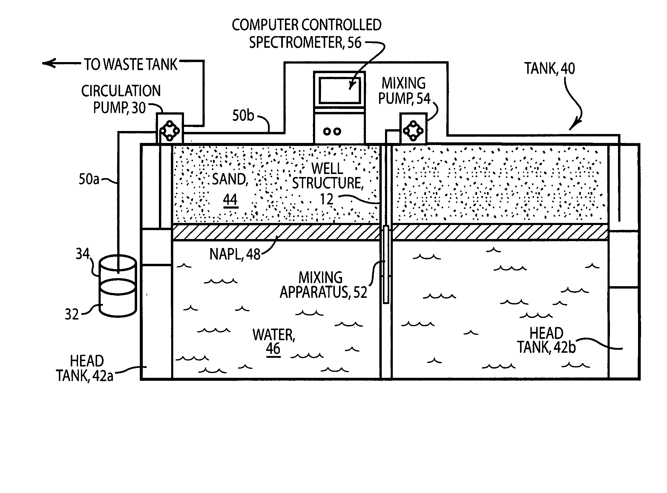
[0075]Larger scale tests were performed to test the NAPL tracer dilution technique on a scale similar to that found in the field. Tank tests were conducted with LNAPL flows of between 0.035 m3 / m / yr and 7.2 m3 / m / yr, and LNAPL thicknesses in the formation of between 9 and 24 cm. Objectives of these tests included: (1) Demonstration that the tracer dilution technique may be applied to LNAPL to predict flow rate through a well; (2) Determination that the accuracy of the tracer dilution method could predict meaningful LNAPL flow rates; (3) Investigation of the range of flow rates for which the method can be applied; and (4) Understanding LNAPL flow convergence around an observation well.

[0076]Steel tank, 40, schematically illustrated in FIG. 4 hereof, was 1.2 m high (4 ft.), 2.4 m wide (8 ft.) and 0.15 m thick (0.5 ft.), and had a single glass face. Head tanks, 42a and 42b, were installed at each end to introduce, recover and monitor fluid levels. Tank 40 was filled with uniform sand, 44...

example 2

[0095]Field experiments using the tracer dilution method of the present invention were undertaken to measure LNAPL flow in a site along the south bank of the North Platte River northeast of Casper, Wyo. impacted by NAPL releases. To contain and clean up these contaminated areas, recovery wells and hydraulic barriers have been installed; in total, more then one million gallons of NAPL have been recovered from the North Platte Alluvium. Among the potential end points for the recovery operations discussed would be when the remaining NAPL has reached an inconsequential flow rate. The present invention was tested in five locations: one location was near a recovery well where the NAPL flow was anticipated to be high, while the others were in a potentially stable region where the NAPL flow was likely to be lower. The selected wells were monitored weekly in an attempt to resolve the stability of the fluid levels prior to conducting the tests. The equipment used in the field study is describ...


PUM


Abstract

A method and apparatus for measuring in situ flow of non-aqueous phase liquids (NAPLs) through a porous medium is described. A tracer is introduced into a well or boring located in the medium and the tracer concentration in the well kept uniform by mixing. The rate at which the tracer is depleted from the well has been determined to be proportional to the flow rate of the NAPL through the well or boring and surrounding formation.

Description

FIELD OF THE INVENTION[0001]The present invention relates generally to the measurement of flow of liquids through porous media and, more particularly, to the measurement of flow of non-aqueous phase liquids (NAPLs) through porous media underlying a site where a chemical release has occurred by measuring the concentration of a tracer introduced into a well or boring located within the site and in the path of the flow, as a function of time.BACKGROUND OF THE INVENTION[0002]Non-aqueous phase liquids include a range of industrial chemicals that are basic building blocks of a modern society. Non-aqueous emphasizes the fact that the liquids are immiscible with water. Two common classifications of NAPL are Light Non-Aqueous Phase Liquids (LNAPL) and Dense Non-Aqueous Phase Liquids (DNAPL), the light and dense prefixes denoting the fluid density compared to that of water; LNAPL will float on water, while water will float on DNAPL. Common examples of NAPL include fuels, solvents, lubricants,...

Claims


Application Information

Patent Timeline
Patent Type & Authority Patents(United States)
IPC IPC(8): G01F1/704
CPCB09C1/00G01F1/704E21B47/1015E21B47/11
Inventor SALE, THOMAS C.TAYLOR, GEOFFREY R.LYVERSE, MARK
Owner CHEVROU USA INC
Why Eureka
Try Eureka