Seat structure

a seat cushion and seat technology, applied in the field of seats, can solve the problems of difficult to obtain favorable vibration absorption qualities, insufficient rigidity, and damage to the seat occupant, and achieve the effects of improving the overall vibration and impact absorption qualities of the seat, increasing the tension, and increasing the dampening effect of the seat cushion

Active Publication Date: 2007-10-16
DELTA TOOLING CO LTD
View PDF20 Cites 49 Cited by
  • Summary
  • Abstract
  • Description
  • Claims
  • Application Information

AI Technical Summary

Benefits of technology

[0009]In light of the above circumstances, the present invention provides a seat with improved safety where, even if the seatback frame is made to be thin, rigidity is ensured.

Problems solved by technology

Since the rigidity of the back portion frame is high with this type of vehicle seat, shock absorption by frame deformation during collision is not achieved and the force of the shock (i.e., acceleration) is conveyed to the person seated in the chair as is with no reduction, and there are concerns that it might impart damage to the seat occupant.
Further, since the rigidity of the back portion frame is high with this type of vehicle seat, vibration absorption depends on the cushion material provided at the back portion frame and forming the backrest, so it has been difficult to obtain favorable vibration absorption qualities.
Nevertheless, with this type of vehicle seat, when large impact force acts upon it directly, as, for example, is the case when the front portion of the vehicle collides into something (front collision) and cargo or freight loaded in the luggage compartment or the rear seat collides into the back portion, the rigidity is insufficient.
When plastic deformation of the back portion frame occurs, the survival space of the seat occupant reduces while the shock that accompanies rocking return towards the back of the person cannot be absorbed (i.e., the shock-absorbing stroke is insufficient).
Further, with this kind of vehicle seat, there is insufficient rigidity relative to shock so, for example, at the time of rear collision, there are cases where movement towards the rear relative to the seat of the seat occupant (especially in the pelvis region) cannot be effectively deterred.
Nonetheless, with this vehicle seat, the reinforcing component simply made highly rigid and being free at both ends cannot itself absorb impact so this is only absorbed by the relative movement of the entire seat to the vehicle and by the conveying of shock to the floor of the vehicle and the like.
Further, for this reason the arrangement of the reinforcing component is also limited to the lower part of the back portion, so safety against collision from, as described above, freight and the like during a frontal collision cannot be achieved.

Method used


Image

  • Seat structure
  • Seat structure
  • Seat structure

Examples


second embodiment

[Second Embodiment]

[0079]Next, explanations will be given regarding a vehicle seat 100 of the second embodiment of the present invention based on FIGS. 4 through 8. It should be noted that the parts / portions that are essentially the same as those of the above first embodiment have been given the same numbers as above and explanations thereon have been omitted

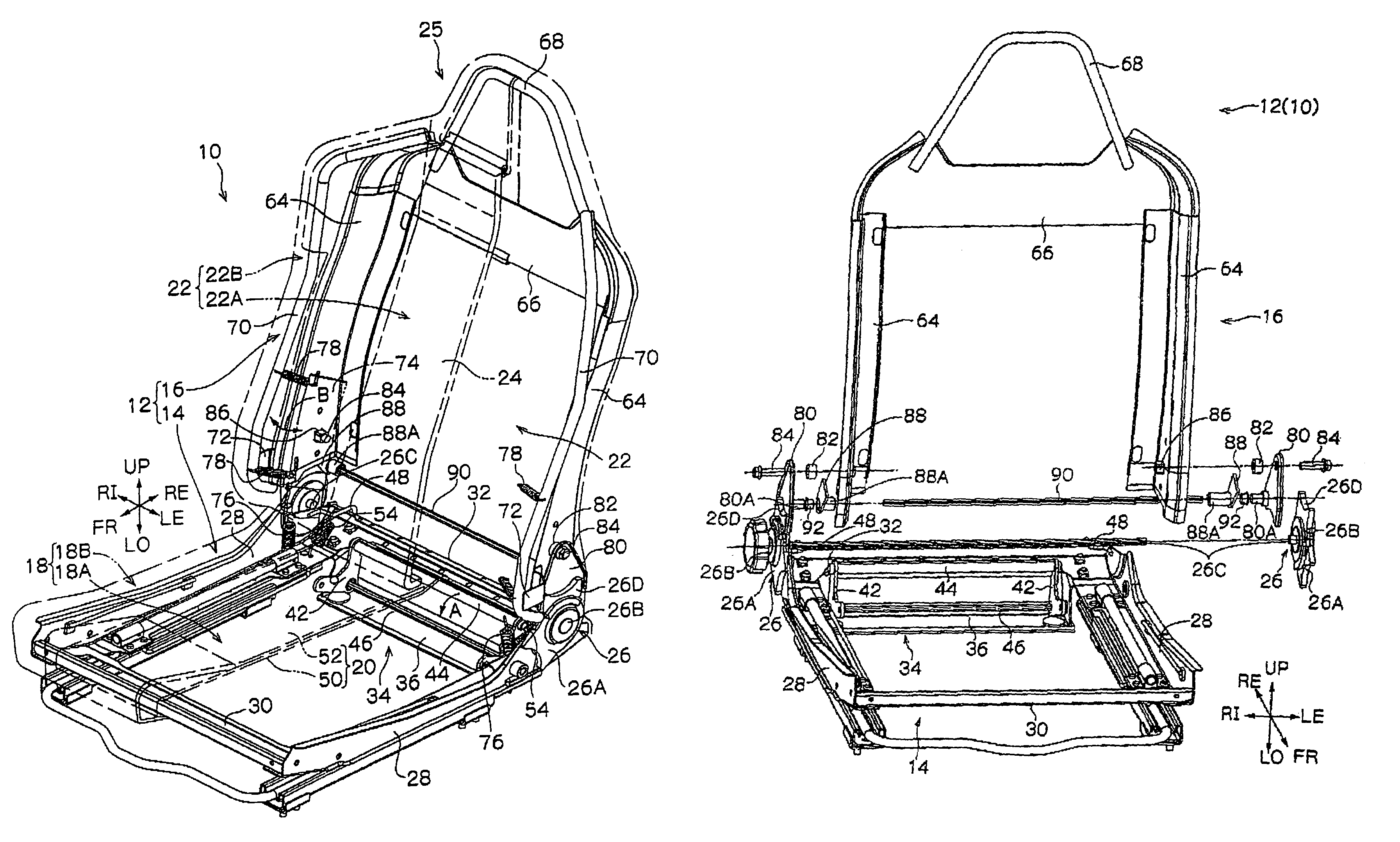
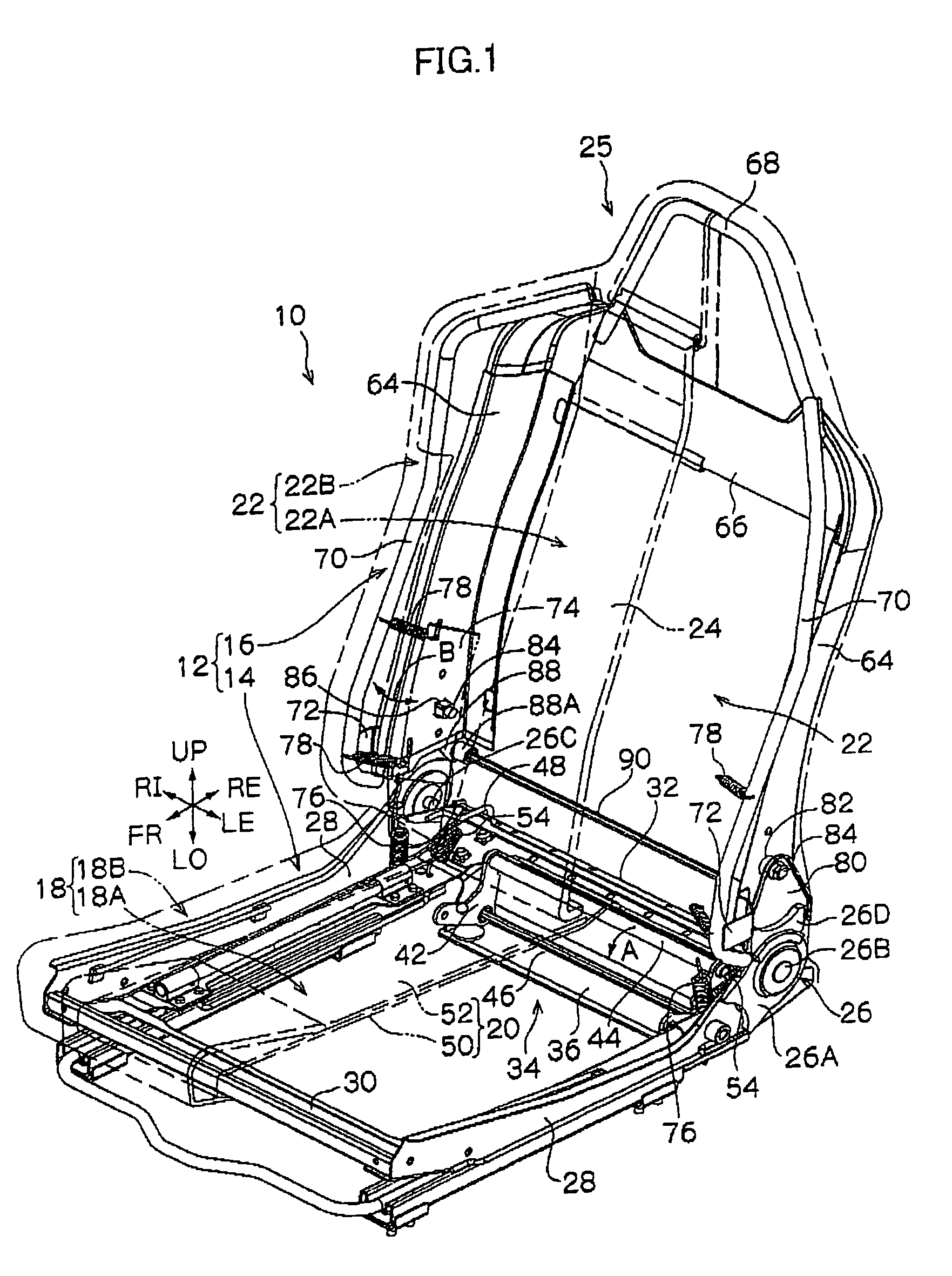
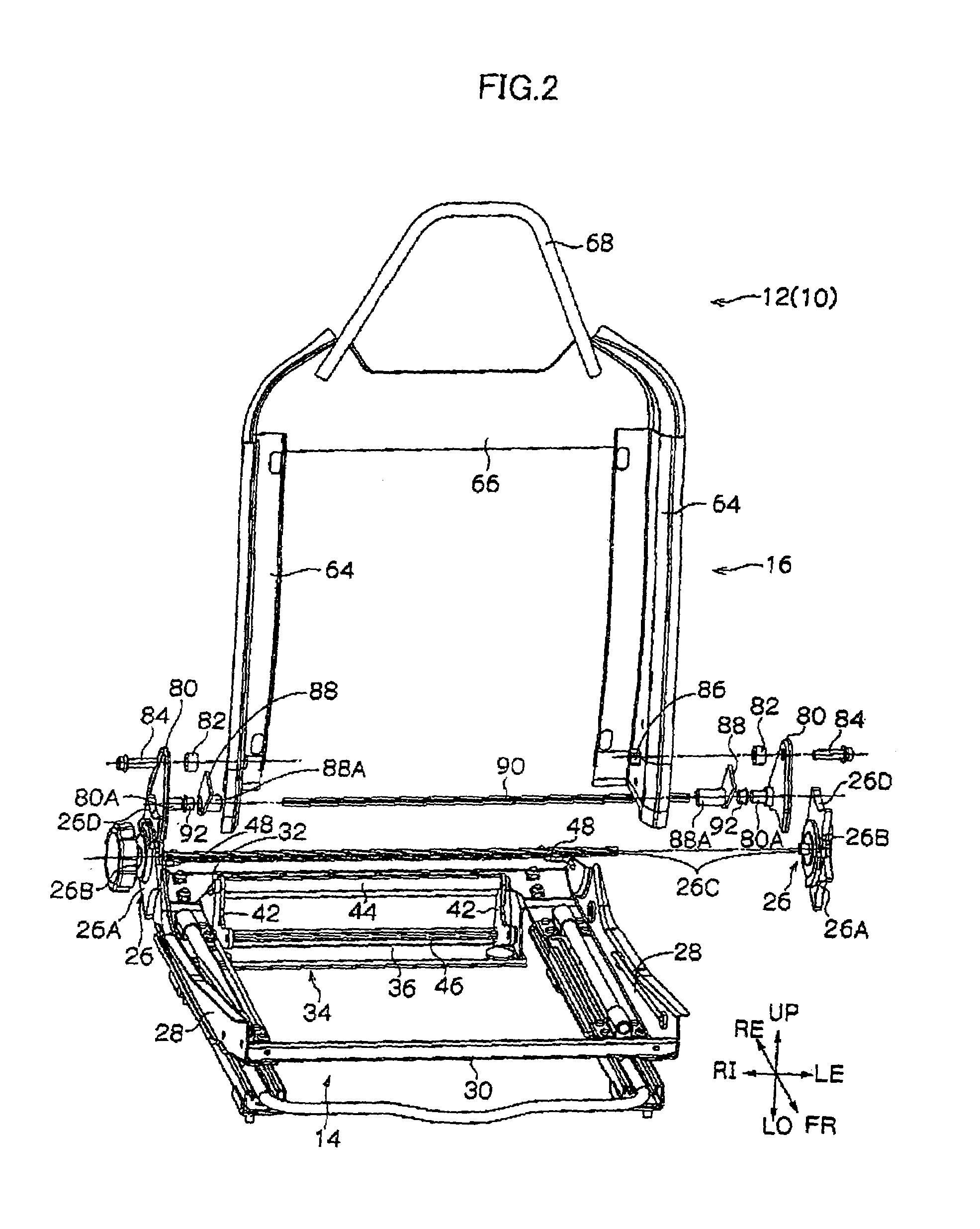
[0080]The outline overall structure of the vehicle seat 100 corresponding to the perspective diagram of FIG. 1 is shown in FIG. 4, and the seat frame 12 forming the vehicle seat 100 is shown as an exploded perspective diagram in FIG. 5. As seen in these drawings, with the vehicle seat 100, the torsion bar 90 is not provided at the seatback frame 16, rather it is provided between the arm components 98 acting as the “turning component” in the present invention and attaching components 80 (seat portion frame 14), and this point differs from the vehicle seat 10 of the first embodiment. Hereafter, detailed explanations will be given....


PUM


Abstract

A vehicle seat is provided with a pair of left and right seatback side frames comprising a seatback frame. The seatback frame is connected to the rear end of a seat portion frame via a reclining mechanism. The vehicle seat is further provided with a torsion bar that is an elastic body between the reclining mechanism and the seatback frame. When the seatback frame displaces and falls forward relative to the seat portion frame, the torsion bar deforms and resists the displacement of the seatback frame. The torsion bar is arranged at the upper region of the seat occupant's pelvis.

Description

CROSS-REFERENCE TO RELATED APPLICATION[0001]This application claims priority under 35 USC 119 from Japanese Patent Application No. 2004-198542, the disclosure of which is incorporated by reference herein.BACKGROUND OF THE INVENTION[0002]1. Field of the Invention[0003]The present invention relates to a seat, particularly a vehicle seat mounted in a vehicle such as an automobile.[0004]2. Description of the Related Art[0005]Vehicle seats are configured so that, for example, a back portion (i.e., seatback) is connected to a rear end portion of the seat portion (i.e., seat cushion) so that the tilting positions are adjustable through a reclining mechanism.[0006]A configuration provided with a thick-type back portion frame for ensuring the rigidity of the back portion is known. Since the rigidity of the back portion frame is high with this type of vehicle seat, shock absorption by frame deformation during collision is not achieved and the force of the shock (i.e., acceleration) is conveye...

Claims


Application Information

Patent Timeline
Patent Type & Authority Patents(United States)
IPC IPC(8): B60N2/20B60N2/90
CPCB60N2/22B60N2/4214B60N2/427B60N2/646B60N2/42781B60N2/449B60N2/643B60N2/42718B60N2/986
Inventor FUJITA, ETSUNORITAKATA, YASUHIDE
Owner DELTA TOOLING CO LTD
Why Eureka
Try Eureka