Lighting module assembly and method for a compact lighting device

a lighting device and light module technology, applied in lighting applications, lighting and heating devices, roads, etc., can solve the problems of limiting the versatility of conventional products, and affecting the practicality of lighting devices

Inactive Publication Date: 2007-10-16
BAYCO PRODS
View PDF11 Cites 157 Cited by
  • Summary
  • Abstract
  • Description
  • Claims
  • Application Information

AI Technical Summary

Problems solved by technology

This technology is relatively new, however, and conventional products heretofore have suffered from a number of deficiencies.
For example, current products utilizing light emitting diodes as light sources tend to be highly specialized and suited to only a single use, thus limiting their versatility as lighting devices or instruments for more ordinary uses.
Further, such specialized devices tend to be expensive because of the relatively low production volumes associated with specialized applications.
Moreover, there exist certain lighting applications for which conventional light sources are unsatisfactory because of limitations in brightness, operating life, durability, power requirements, excessive physical size, poor energy efficiency, and the like.
While some presently available products employ these semiconductor light sources, their full potential is frequently not realized.
This may occur because of deficiencies in optical components and drive circuits, or interface components having particular combinations of structure and function are not available.

Method used


Image

  • Lighting module assembly and method for a compact lighting device
  • Lighting module assembly and method for a compact lighting device
  • Lighting module assembly and method for a compact lighting device

Examples


Embodiment Construction

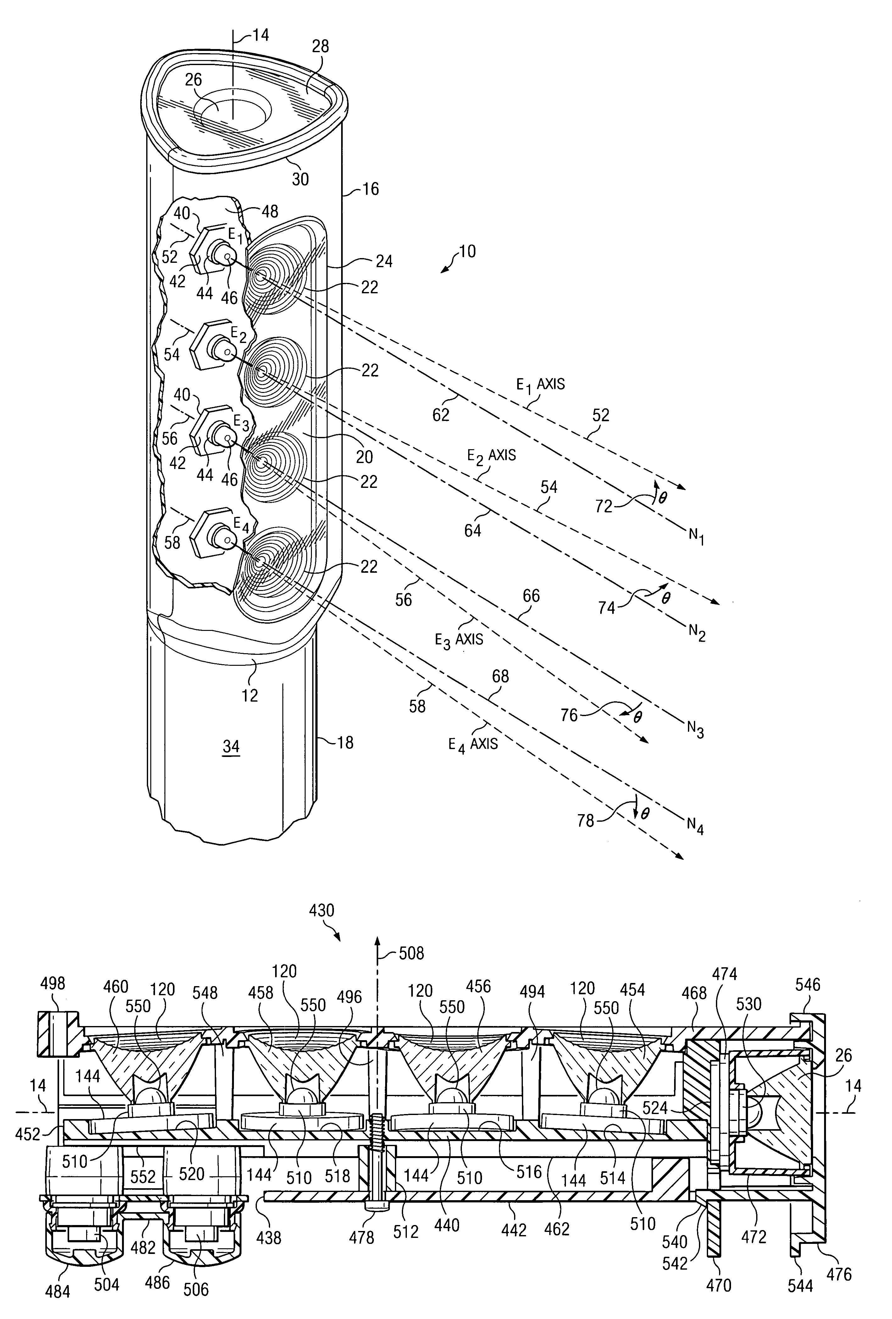
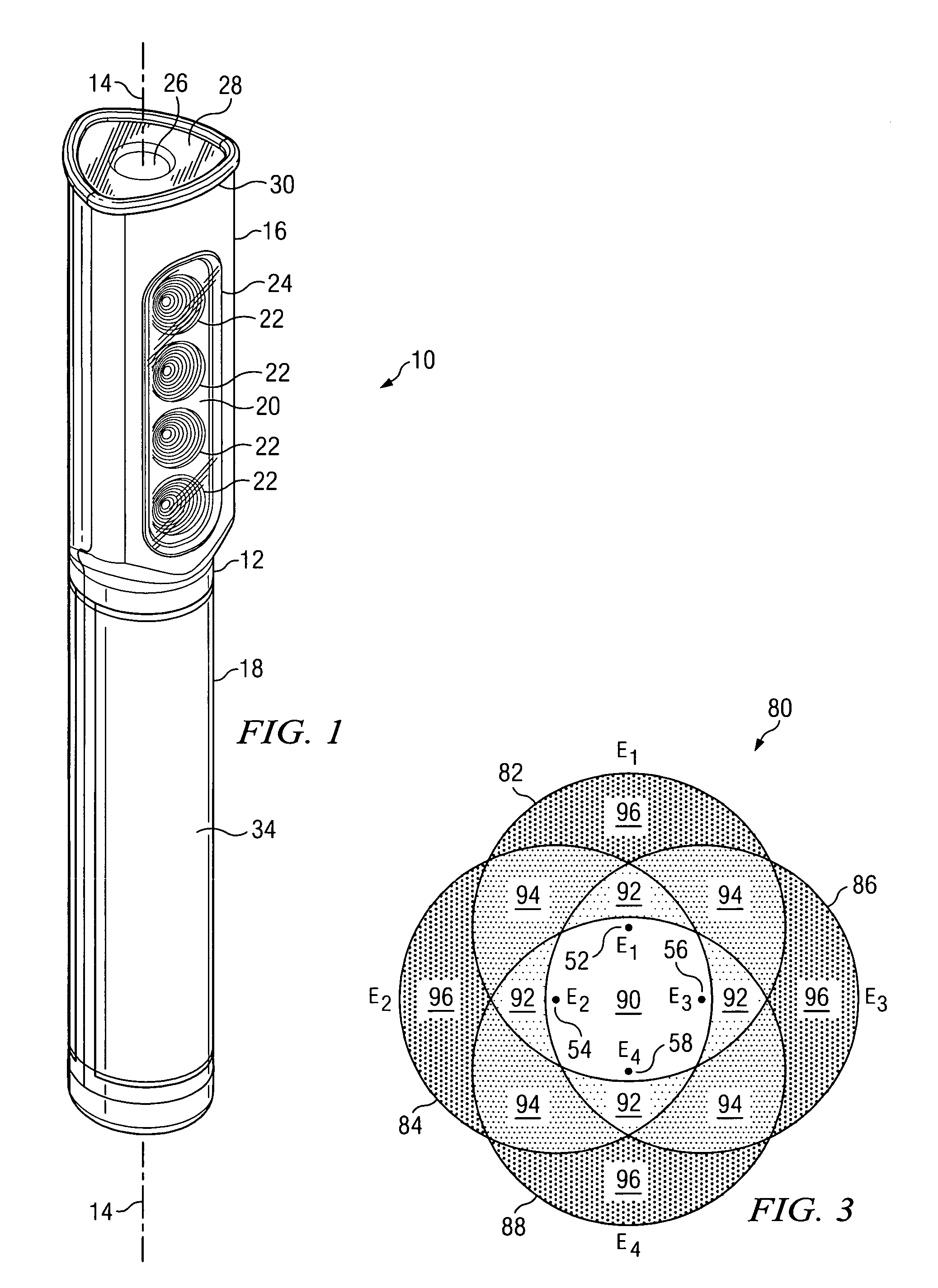
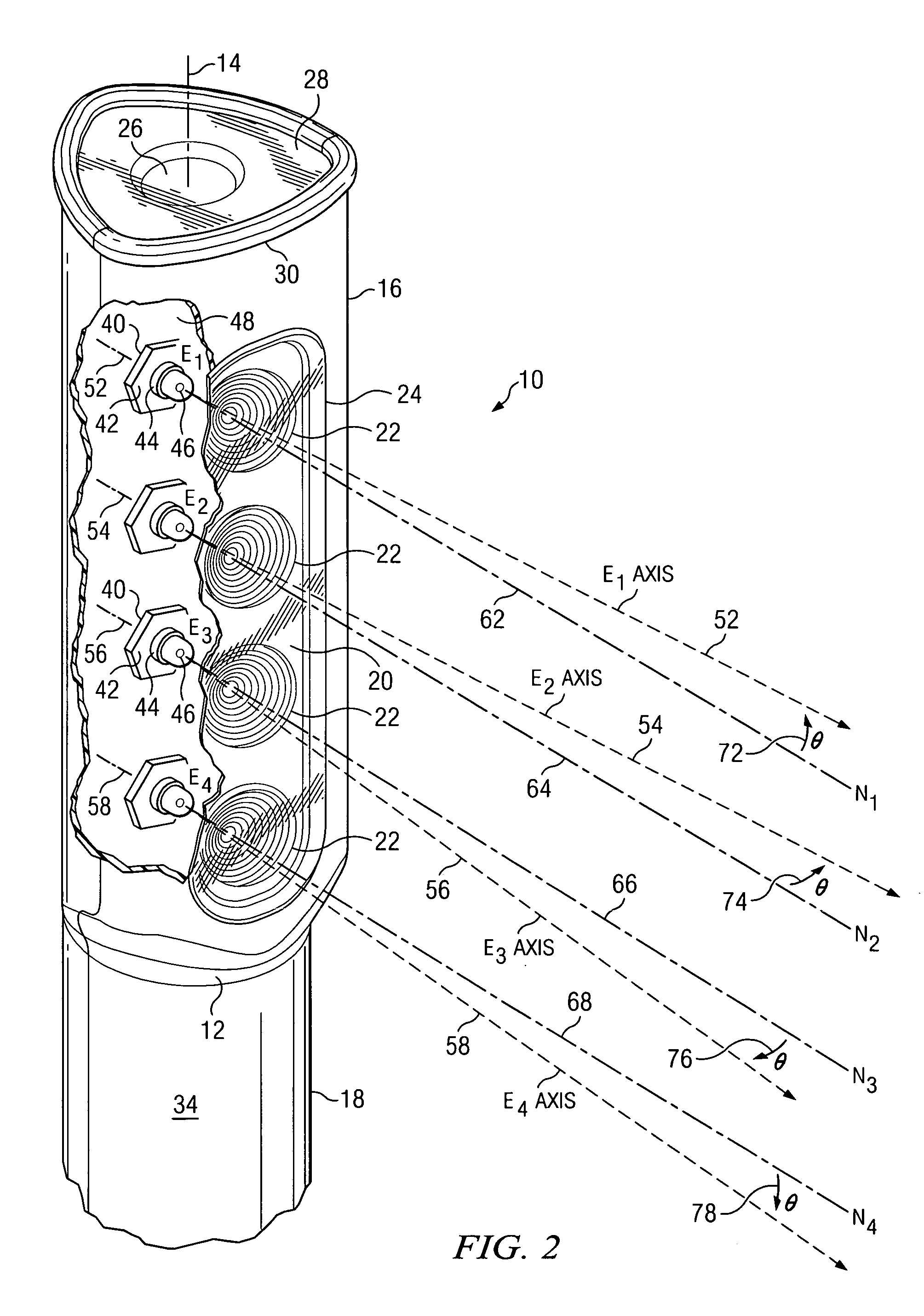
[0030]Referring to FIG. 1, there is illustrated one embodiment of a perspective view of a portable, combination task lamp and flash light (also referred to herein as a portable lighting device 10 or “PLD 10,” that provides both flood and spot light illumination, and is constructed according to the present invention. The PLD 10 includes an elongated tubular housing 12 defined along a longitudinal axis 14, having a first section 16 at a first end for containing a plurality of light emitting assemblies or light sources 22, and further having a second section 18 at a second end for containing a power supply (See FIG. 7). Visible through a clear side lens 24 in FIG. 1 is a bezel 20 that locates the forward surfaces of four light sources 22 substantially in a row. The side lens 24 is an internal component of the housing 12 as will be further described with FIG. 7. The row of four light sources 22 may be denoted as a first directed array of light sources 22. Any number of individual light ...


PUM


Abstract

A plurality of compact light emitting assemblies is mounted on a frame configured as a heat sink that provides a structural platform and a thermal management component. The frame further ensures proper alignment of the light emitting devices to aim the individual light emitting assemblies in a direction that provides a predetermined overlap of the individual light beams resulting in a uniform, high brightness pattern on a target surface. The source of current connected to the light emitting devices may also be mounted on the frame. The compact light emitting module thus provided is readily adaptable to a variety of compact, high performance lighting product configurations.

Description

BACKGROUND OF THE INVENTION[0001]1. Field of the Invention[0002]The present invention generally relates portable lighting apparatus and, more particularly, to optical, mechanical, and electrical features for the design, utility, and performance of portable task lighting and flash light apparatus using very small light emitting devices.[0003]2. Description of the Prior Art[0004]Lighting devices can be grouped into two basic applications: illumination devices and signaling devices. Illumination devices enable one to see into darkened areas. Signaling devices are designed to be seen, to convey information, in both darkened and well-lit areas. Widely available varieties of portable lighting apparatus, which may combine both the illumination type and the signaling type, employ a variety of lighting technologies in products such as task lamps and flashlights. Each new development in technology is followed by products that attempt to take advantage of the technology to improve performance ...

Claims


Application Information

Patent Timeline
Patent Type & Authority Patents(United States)
IPC IPC(8): F21V5/00
CPCF21L4/02F21V13/045F21V29/004F21V29/76F21V29/75F21W2111/04F21Y2101/02F21W2111/02F21Y2115/10F21V29/70
Inventor BAYAT, BIJANNEWTON, JAMES
Owner BAYCO PRODS
Why Eureka
Try Eureka