Electrical connector

a technology of electrical connectors and connectors, applied in the direction of coupling devices, two-part coupling devices, electrical apparatus, etc., can solve the problems of low holding ability, poor electrical conductivity, unstable, etc., and achieve the effect of enhancing holding ability and enhancing conducting

Active Publication Date: 2007-10-16
LOTES
View PDF2 Cites 2 Cited by
  • Summary
  • Abstract
  • Description
  • Claims
  • Application Information

AI Technical Summary

Benefits of technology

[0007]In comparison with current technologies, the novel electrical connector according to the present invention can increase holding ability and the conducting effect is enhanced, accordingly.

Problems solved by technology

However, there is no element to hold the terminal while butting, the holding ability is low and unstable.
Consequently, the electrical conductivity is poor.

Method used


Image

  • Electrical connector
  • Electrical connector
  • Electrical connector

Examples


Embodiment Construction

[0019]In order to make the structure and characteristics as well as the effectiveness of the present invention to be further understood and recognized, the detailed description of the present invention is provided as follows along with preferred embodiments and accompanying figures.

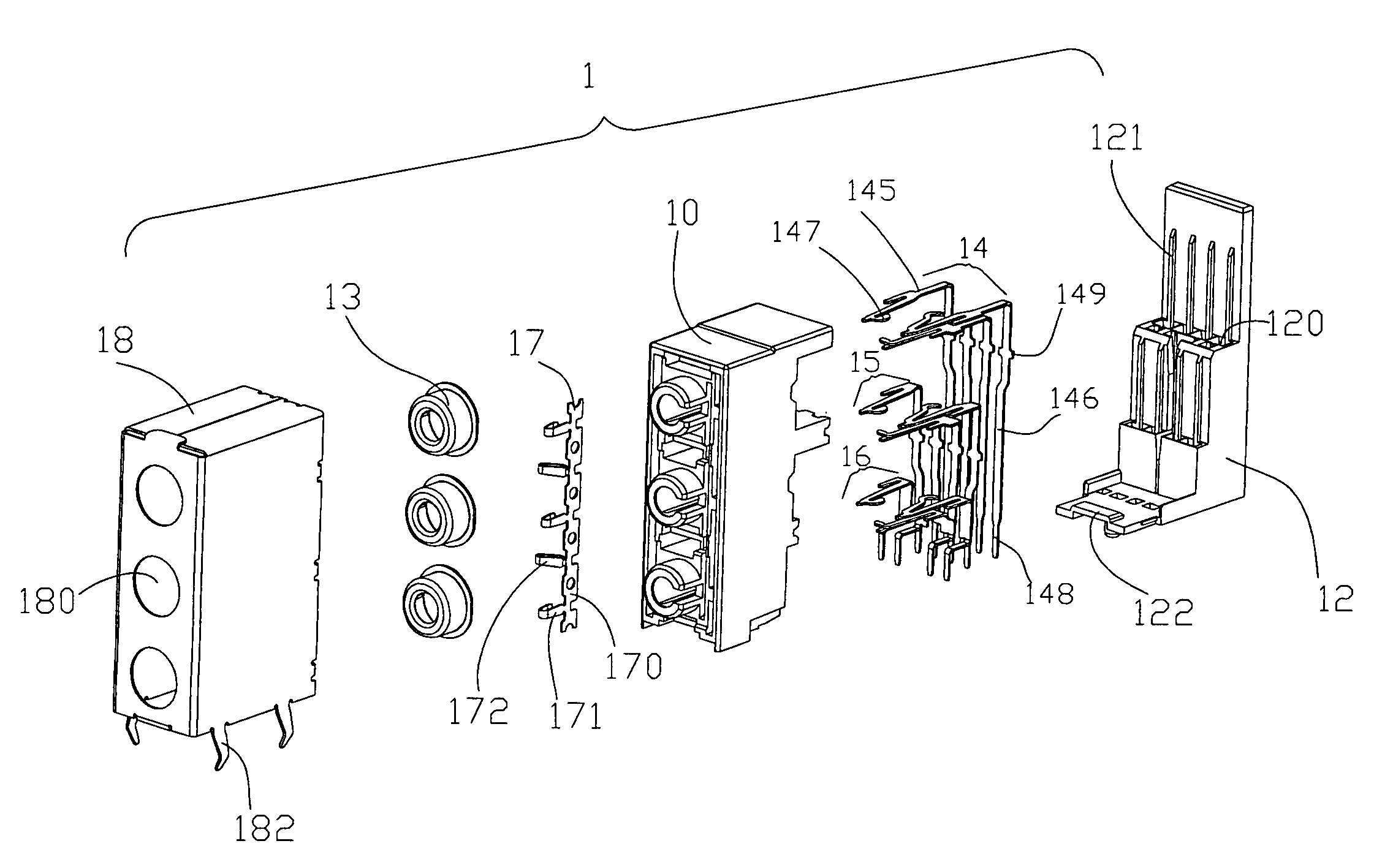
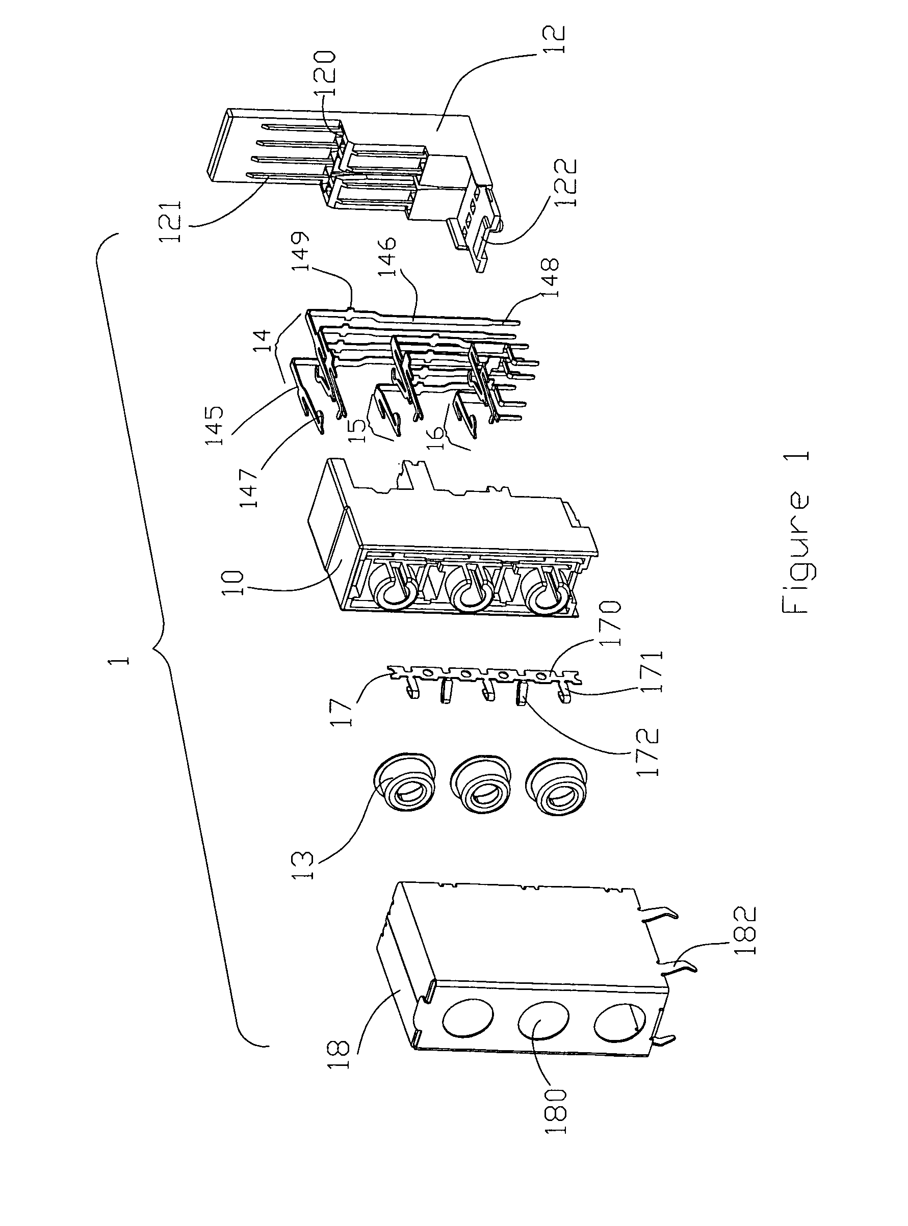
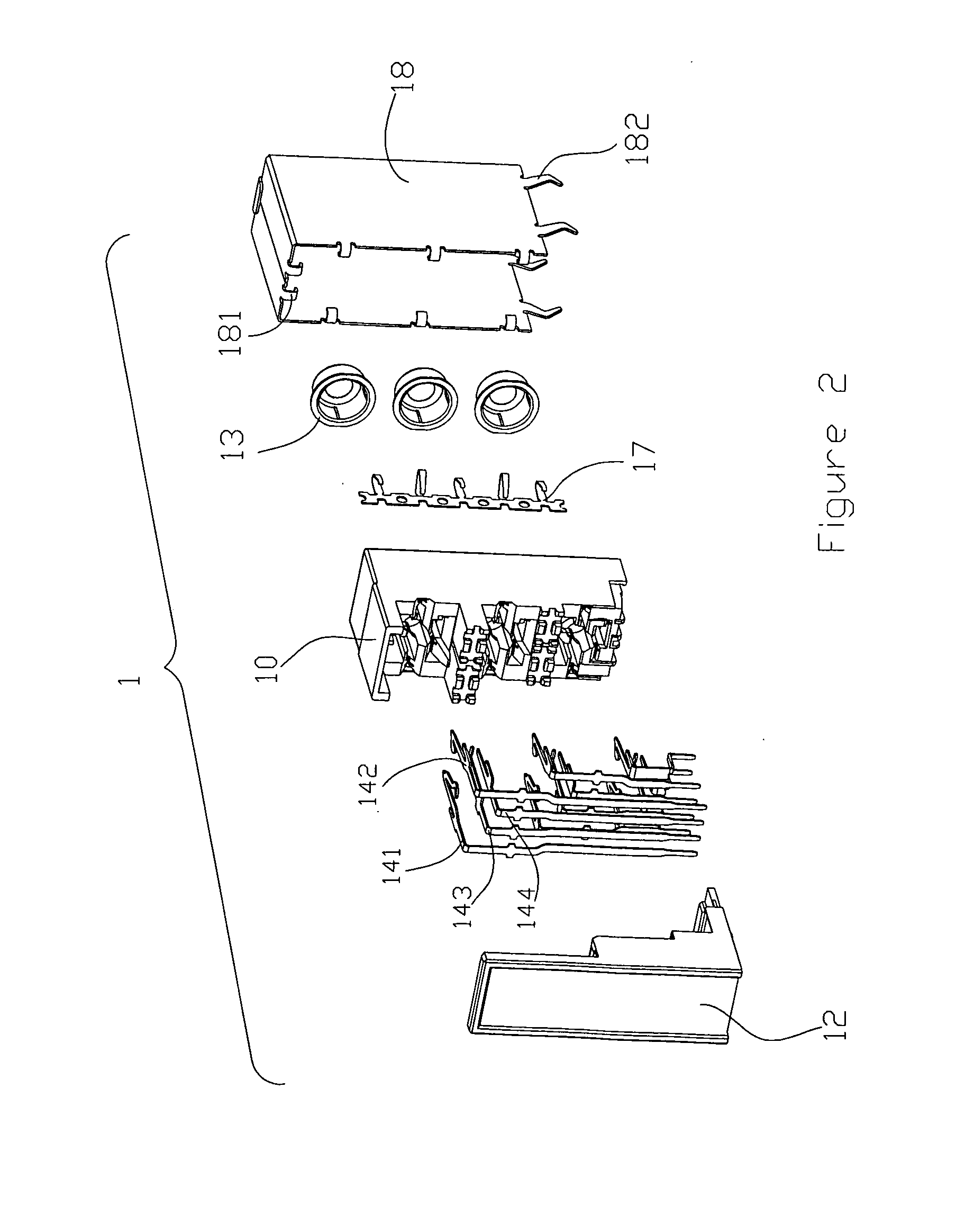
[0020]As shown in FIGS. 1 to 8, an electrical connector 1 according to the present invention is an audio jack connector, which connects with an external electronic device (a plug 2) for realizing transmission of audio signals. The electrical connector 1 includes an insulation body 10, a back base 12, a plurality of rings 13, three sets of terminal sets 14, 15, 16 arranged in a line (upper, middle, and lower) with four terminals in each of the terminal sets, a grounding electrode 17 with a plurality of grounding terminals thereon, and a sheltering housing 18 covering the insulation body 10 and the back base 12.

[0021]Jacks 100 are adapted on the insulation body 10 for butting with the plug 2 and are arrange...


PUM


Abstract

The present invention relates to an electrical connector, which includes jacks for accommodating external electronic devices. A plurality of terminals and an extruding arm for extruding the external electronic device, which extruding arm is an insulator and moves elastically, are adapted in the jacks. Thereby, the holding ability is increased and hence the conducting effect is enhanced.

Description

FIELD OF THE INVENTION[0001]The present invention related to a connector, and particularly to an electrical connector applied in audio jacks.BACKGROUND OF THE INVENTION[0002]With technological development in various electronic products and multimedia personal computers, the applications of audio jack connectors prevail in the industries described above increasingly. In addition, different kinds of electronic products expand their peripheral equipments, and thereby the demand in performance of audio jack connectors increases as well.[0003]An audio jack connector is disclosed in U.S. Pat. No. 6,062,885, wherein the electrical switching device includes a first switching terminal and a second switching terminal. A body is adapted to the first switching terminal, which is suspended on an elastic terminal arm adapted on the back of the body. In normal conditions, that is, when there is no butting plug inserted, the second switching terminal contacts with the elastic terminal arm of the fi...

Claims


Application Information

Patent Timeline
Patent Type & Authority Patents(United States)
IPC IPC(8): H01R24/04H01R24/58
CPCH01R13/6315H01R25/006H01R24/58H01R13/6597H01R2107/00H01R13/659
Inventor JU, TED
Owner LOTES
Why Eureka
Try Eureka