Z-filter media with reverse-flow cleaning systems and methods

a technology of reverse-flow cleaning and filter media, applied in the field of z-filter media, filter elements, systems and methods with reverse-flow cleaning, can solve the problems of affecting the flow rate of the desired flow, too little fluid flow through, and contaminant load over time,

Active Publication Date: 2007-10-16
DONALDSON CO INC
View PDF38 Cites 164 Cited by
  • Summary
  • Abstract
  • Description
  • Claims
  • Application Information

AI Technical Summary

Problems solved by technology

The filter media used for the purification, over time, will load with contaminant.
Either too little fluid is allowed to flow through, or too much work is required to move the desired flow due to the higher restriction.

Method used


Image

  • Z-filter media with reverse-flow cleaning systems and methods
  • Z-filter media with reverse-flow cleaning systems and methods
  • Z-filter media with reverse-flow cleaning systems and methods

Examples


Embodiment Construction

A. FIGS. 1 and 2, System of Use

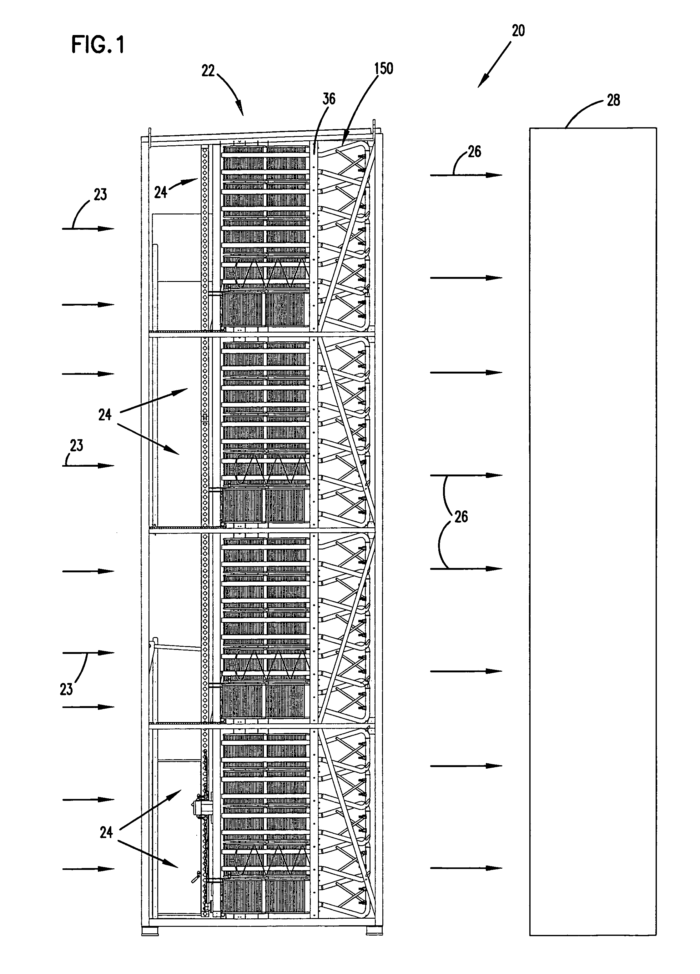
[0024]The methods of use, gas cleaner arrangements, and constructions disclosed herein are useable with a variety of systems. FIGS. 1 and 2 depict one example system. In this case, the example system shown is a gas turbine system. The gas turbine system is shown in FIG. 1 schematically at 20.

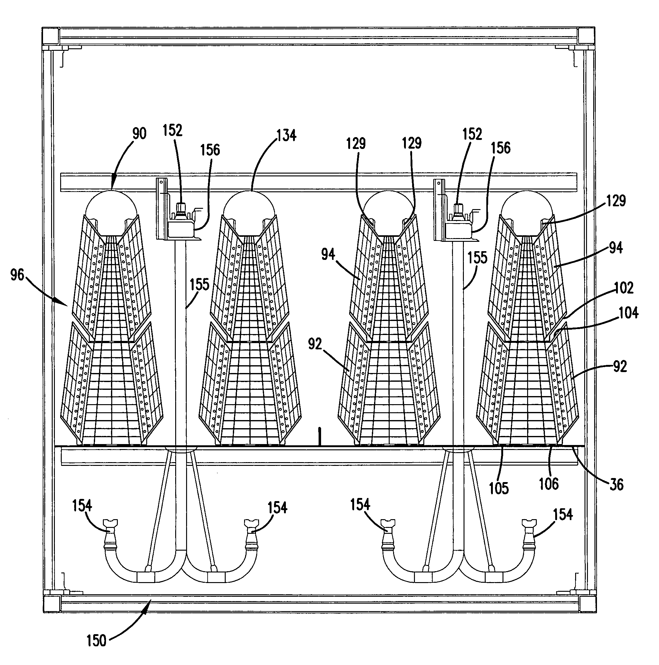
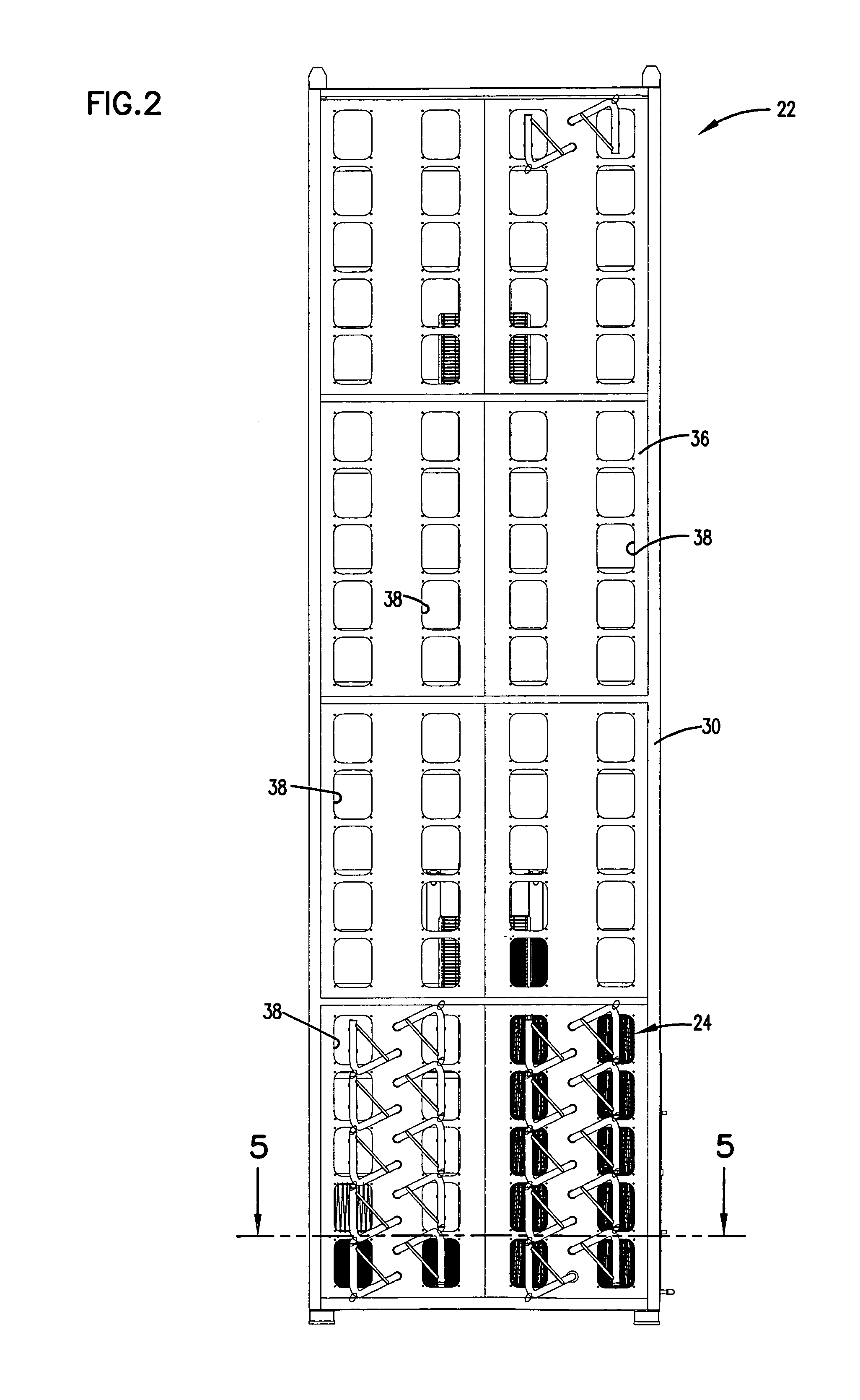
[0025]In FIG. 1, gas, such as air, is shown drawn into an air intake system 22 at arrows 23. The air intake system 22 includes a plurality of gas filter arrangements 24 generally held in a tube sheet 36.

[0026]The air is cleaned in the gas filter arrangements 24, and then it flows downstream at arrows 26 into gas turbine generator 28, where it is used to generate power.

[0027]It should be understood that in FIG. 2, only a portion of the air intake system 22 is depicted. This is for purposes of clarity and explanation.

B. Overview of Gas Filter Arrangement, System, and Method

[0028]FIG. 3 depicts a schematic, perspective, partially exploded view of a portion of the air ...


PUM

PropertyMeasurementUnit
angleaaaaaaaaaa
diameteraaaaaaaaaa
radiusaaaaaaaaaa

Abstract

A method for cleaning a filter having Z-media includes providing a filter having Z-media and cleaning the media construction by directing a pulse of compressed gas into the media construction through the downstream flow face. Filter elements useable with such methods include elements made of Z-media. An example system utilizing the method includes a gas turbine air intake system.

Description

CROSS-REFERENCE TO RELATED APPLICATIONS[0001]This application claims the benefit of U.S. Provisional Application No. 60 / 432,923, filed on Dec. 11, 2002, which application is herein incorporated by reference.[0002]This application is related to a U.S. utility patent application No. 10 / 731,556, entitled REVERSE-FLOW CLEANING SYSTEMS AND METHODS, which application is being filed concurrently herewith and incorporated herein by reference.TECHNICAL FIELD[0003]This disclosure relates to Z-filter media, filter elements, systems, and methods. In particular, this disclosure relates to Z-filter media, filter elements, systems, and methods with reverse-flow cleaning, such as pulse cleaning. In certain examples described, this disclosure relates to filtering of gas useful with gas turbine systems.BACKGROUND[0004]Filters are used to purify a variety of fluids, including gas and liquid. The filter media used for the purification, over time, will load with contaminant. Filters are used until they ...

Claims


Application Information

Patent Timeline
Patent Type & Authority Patents(United States)
IPC IPC(8): B01D39/16B01D46/02B01D46/00B01D46/24B01D46/42B01D46/52
CPCB01D46/0068B01D46/125B01D46/2414B01D46/526B01D46/525Y10T29/49826B01D2279/60B01D46/121B01D46/71
Inventor SPORRE, TIMOTHY D.ROTHMAN, JIM C.HANDLEY, MICHAEL W.RAETHER, THOMAS D.
Owner DONALDSON CO INC
Why Eureka
Try Eureka