
Car wash blower control

a technology for blowers and cars, applied in the direction of machines/engines, vehicle cleaning, lighting and heating apparatus, etc., can solve the problems of increasing load, motors and impellers remain under load, and are generally very detrimental to electric motors, so as to reduce maintenance, less electrical energy, and less wear and tear

Active Publication Date: 2007-10-23
PROTO VEST
View PDF12 Cites 4 Cited by
  • Summary
  • Abstract
  • Description
  • Claims
  • Application Information

AI Technical Summary

Benefits of technology

[0008]Accordingly, the subject invention allows the electric motor to be run continuously but without a load as air is unavailable through the inlet to compress or pump. Without a load, the motor uses less electrical energy and is subject to less wear and tear, thereby reducing maintenance.

Problems solved by technology

It is generally very detrimental to an electric motor to start and stop the motor.
However, during the idle periods of no demand, the motor and impeller remain under load, and sometimes an increased load because of backpressure.

Method used


Image

  • Car wash blower control
  • Car wash blower control
  • Car wash blower control

Examples


Embodiment Construction

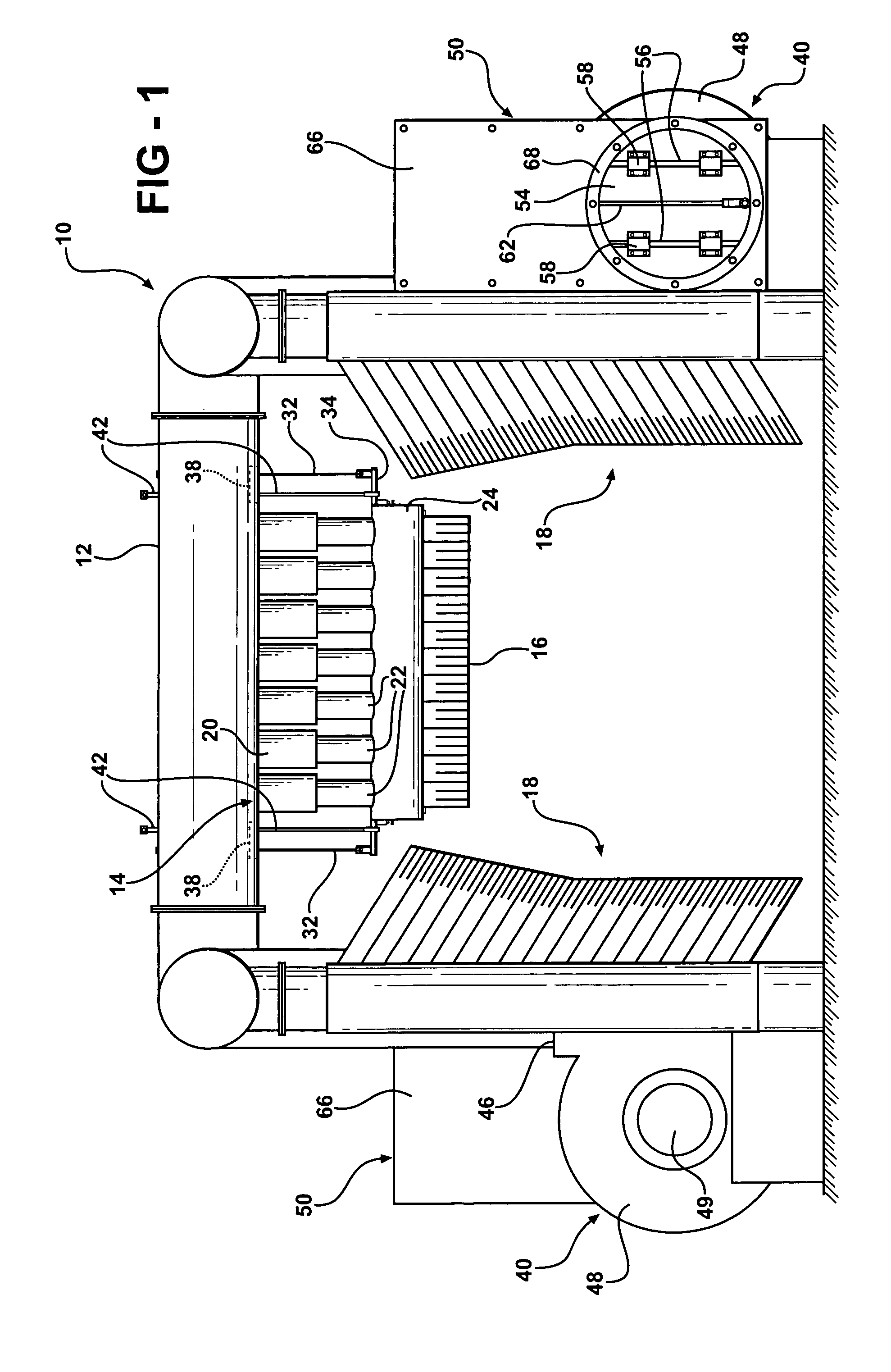
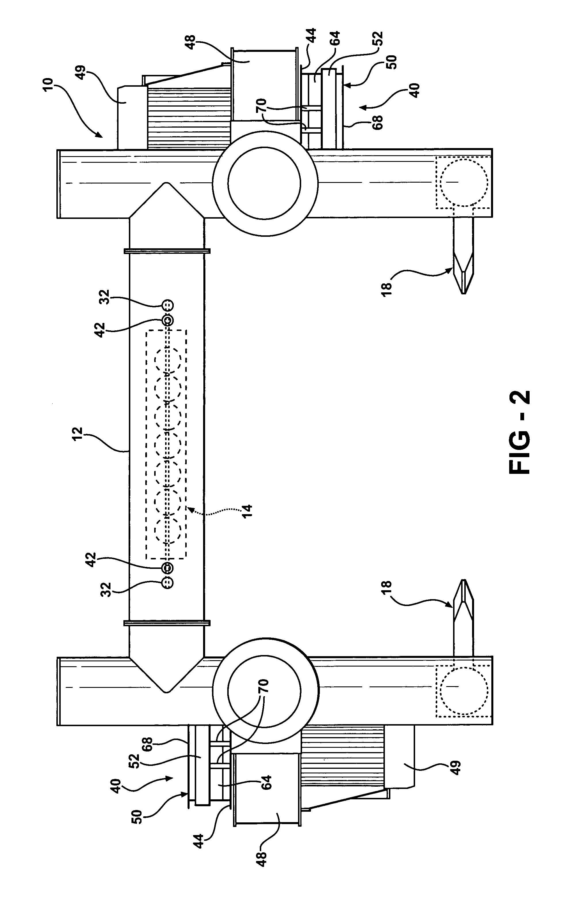
[0019]Referring to the Figures, wherein like numerals indicate like parts throughout the several views, an assembly for blowing liquids from a vehicle is generally shown at 10.

[0020]The assembly comprises a support plenum 12 for distributing air. A nozzle system is generally indicated at 14 and includes a nozzle 16 for directing air toward the top of a vehicle. The nozzle 16 comprises a flexible material, such as a fabric as is well known in the art. In addition, the assembly includes side nozzles systems, generally shown at 18 for directing air from the side legs of the plenum 12, as is well known and shown in the aforementioned U.S. Pat. No. 5,960,564.

[0021]As more specifically described in application Ser. No. 09 / 849,165 filed May 04, 2001, now U.S. Pat. No. 6,519,872, an air delivery conduit, including a plurality of pairs of telescoping tubes 20 and 22, interconnects the plenum 12 and the nozzle system 14 for delivering air from the plenum 12 to the nozzle system 14 while allow...


PUM


Abstract

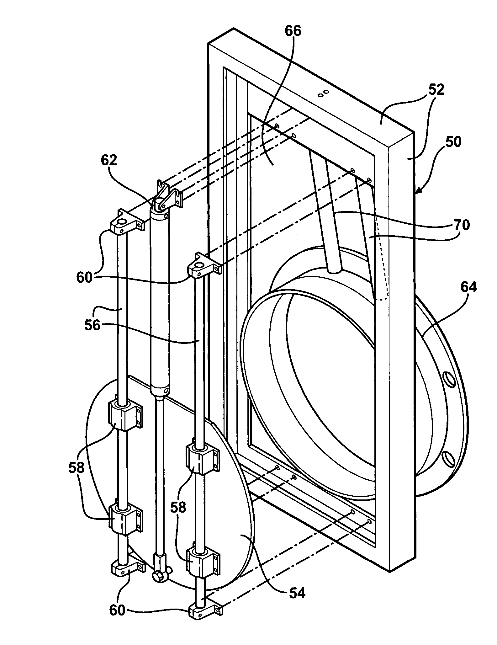
A valve plate (54) is slidably moved on a frame (52) by an actuator (62) between open and closed positions to control the supply of air sucked into the inlet (44) of a blower system (40) that supplies pressurized air through an outlet (46) to a plenum (12) for distribution to said nozzle (16, 18). By disposing the valve plate (54) at the inlet, the blower motor (49) may run continuously without a load as the impeller is not pumping air when there is no demand to blow the water from a vehicle.

Description

CROSS-REFERENCES TO RELATED APPLICATIONS[0001]This application claims the benefit of provisional application 60 / 477,550 filed Jun. 11, 2003.BACKGROUND OF THE INVENTION[0002]1. Field of the Invention[0003]The subject invention relates to an assembly for blowing liquids from the surface of a vehicle in a car wash.[0004]2. Description of the Related Art[0005]Assemblies for blowing liquids from a vehicle are well known and typically include a plenum for distributing air to a plurality of nozzles that direct air from the plenum toward a vehicle. The plenum is supplied air by a blower system having an inlet for sucking air in and an outlet for supplying pressurized air to the plenum for distribution to the nozzles. Such blowers include an impeller that is rotated in a housing by an electric motor, the impeller acting as a pump or compressor to pressurize air and force it into the plenum system.[0006]There are significant periods during the operation of a car wash that there is no demand f...

Claims


Application Information

Patent Timeline
Patent Type & Authority Patents(United States)
IPC IPC(8): F26B21/00B60S3/00F04D27/02
CPCF04D27/003B60S3/002
Inventor MCELROY, CHRISTOPHER PATRICK
Owner PROTO VEST
Learn More