Device for controlling a hydraulic accumulator of a hydraulic system

a technology of hydraulic system and hydraulic accumulator, which is applied in the direction of valve operation/release device, service pipe system, functional valve type, etc., can solve the problems of reducing the service life of the mechanical pump, affecting the operation of the electrical system, and affecting the operation of the mechanical pump. , to achieve the effect of reducing the cost of the electrical system, reducing the amount of electrical energy, and reducing the possibility of device expansion

Inactive Publication Date: 2015-08-04
ROBERT BOSCH GMBH
View PDF20 Cites 5 Cited by
  • Summary
  • Abstract
  • Description
  • Claims
  • Application Information

AI Technical Summary

Benefits of technology

[0014]The present invention has the advantage that a hydraulic accumulator of a hydraulic system, in particular in automatic transmissions, may be emptied in a controlled manner—and in at least one embodiment also filled in a controlled manner—for carrying out a start-stop function of an internal combustion engine, the wear and susceptibility to contamination being minimal and an electrical energy consumption also being minimal. An example device according to the present invention operates reliably and cost-effectively and may also be manufactured comparatively easily.
[0018]One embodiment of the device provides that the device has a second check valve which is in line with the first check valve and is situated between the first check valve and the system-side port and which is blocking in the direction of the first check valve, and the device also has a bypass situated in parallel to the second check valve, in which a volumetric flow-limiting element is situated. The volumetric flow-limiting element may be designed as a throttle or a diaphragm and, for the sake of simplicity, is always referred to below as “throttle” or “flow throttle.” A throttle has the advantage over a diaphragm that the volumetric flow may be limited comparatively independently of the temperature of the fluid. As a result, the function of the device may be improved in that a filling operation of the hydraulic accumulator is not dependent only on a pressure increase of the hydraulic system with regard to the hydraulic accumulator, but instead is also determined by the bypass via which a controlled filling of the hydraulic accumulator may take place. In particular, a cross section of the bypass limits the amount of fluid flowing to the hydraulic accumulator to a preset value. This is accomplished by the flow throttle situated in the bypass.
[0021]Yet another embodiment of the device provides that a second check valve is situated in parallel to the volumetric flow-limiting element, which is blocking in the direction of the system-side port. The device may thus be effectively improved in that a decoupling, so to speak, takes place between the filling operation and the emptying operation of the hydraulic accumulator. If sufficient hydraulic pressure prevails in the hydraulic system, the second check valve may open in the direction of the control port of the unblockable check valve or in the direction of the control valve or in the direction of the hydraulic accumulator. In this way, it is achieved that the fluid flow for filling the hydraulic accumulator is generally determined by an effective cross section of the control valve. Due to the second check valve, the comparatively small effective cross section of the volumetric flow-limiting element may be bypassed. When emptying the hydraulic accumulator, the second check valve is closed, and the volumetric flow-limiting element limits the fluid flow from the control area of the unblockable check valve in the direction of the system-side port. This advantageously makes it possible for the effective cross section of the volumetric flow-limiting element to be comparatively small, so that the hydraulic pressure in the control area of the unblockable check valve decreases by a comparatively small amount.
[0022]The example device may have a simpler configuration if the second check valve and the volumetric flow-limiting element are situated in a valve element of the first check valve or in a bypass channel of the first check valve. For example, the second check valve and the volumetric flow-limiting element as well as the filter may be situated in a piston of the first check valve. This makes it possible to provide a particularly compact design, which may save installation space and makes the manufacture of the device cheaper.
[0024]The device according to the present invention requires less electrical energy if the control valve is blocked in the de-energized state. The present invention is directed to the consideration that the hydraulic accumulator is emptied during comparatively short time segments during operation of the hydraulic system. Accordingly, the hydraulic device is designed in such a way that no or very little fluid is supplied to the hydraulic system in a de-energized state of the hydraulic accumulator. The possible applications of the device may be advantageously expanded thereby, and the costs of the electrical system are lowered.

Problems solved by technology

The latter is provided by a mechanical pump (i.e., one driven by the internal combustion engine), the pump generally having an overdimensioned design due to the linear dependency of the volumetric flow on the rotational speed and due to reserves provided for taking into account the idling speed of the internal combustion engine and a possibly high oil temperature.
When the internal combustion machine is stopped during the stopping phase, and when the hydraulic pump is stopped, the transmission may no longer be supplied with sufficient pressure or sufficient volumetric flow.
When the internal combustion engine restarts, it takes a certain amount of time before the mechanical pump generates enough pressure again.
This results in a corresponding time delay before a starting torque is transmittable via the clutches.
In addition, undesirable torque jumps may result when the clutches engage uncontrolled or slip.
Furthermore, these clutches are generally not designed for the loads which occur.

Method used


Image

  • Device for controlling a hydraulic accumulator of a hydraulic system
  • Device for controlling a hydraulic accumulator of a hydraulic system
  • Device for controlling a hydraulic accumulator of a hydraulic system

Examples


Embodiment Construction

[0039]The same reference numerals are used for functionally equivalent elements and variables in all figures, even in different specific embodiments.

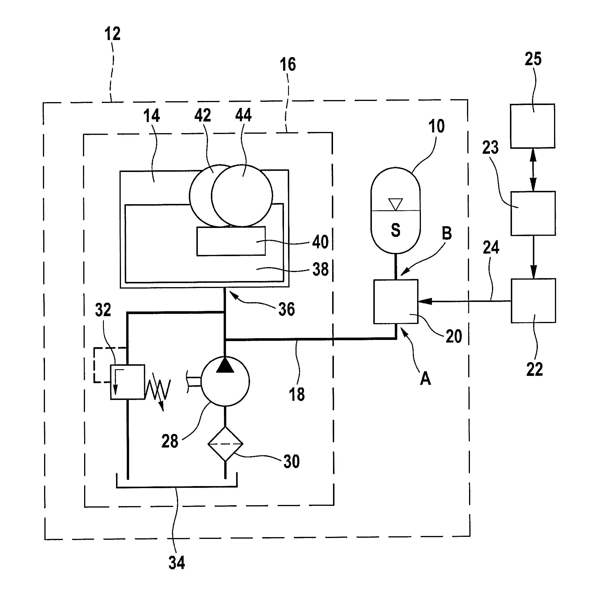
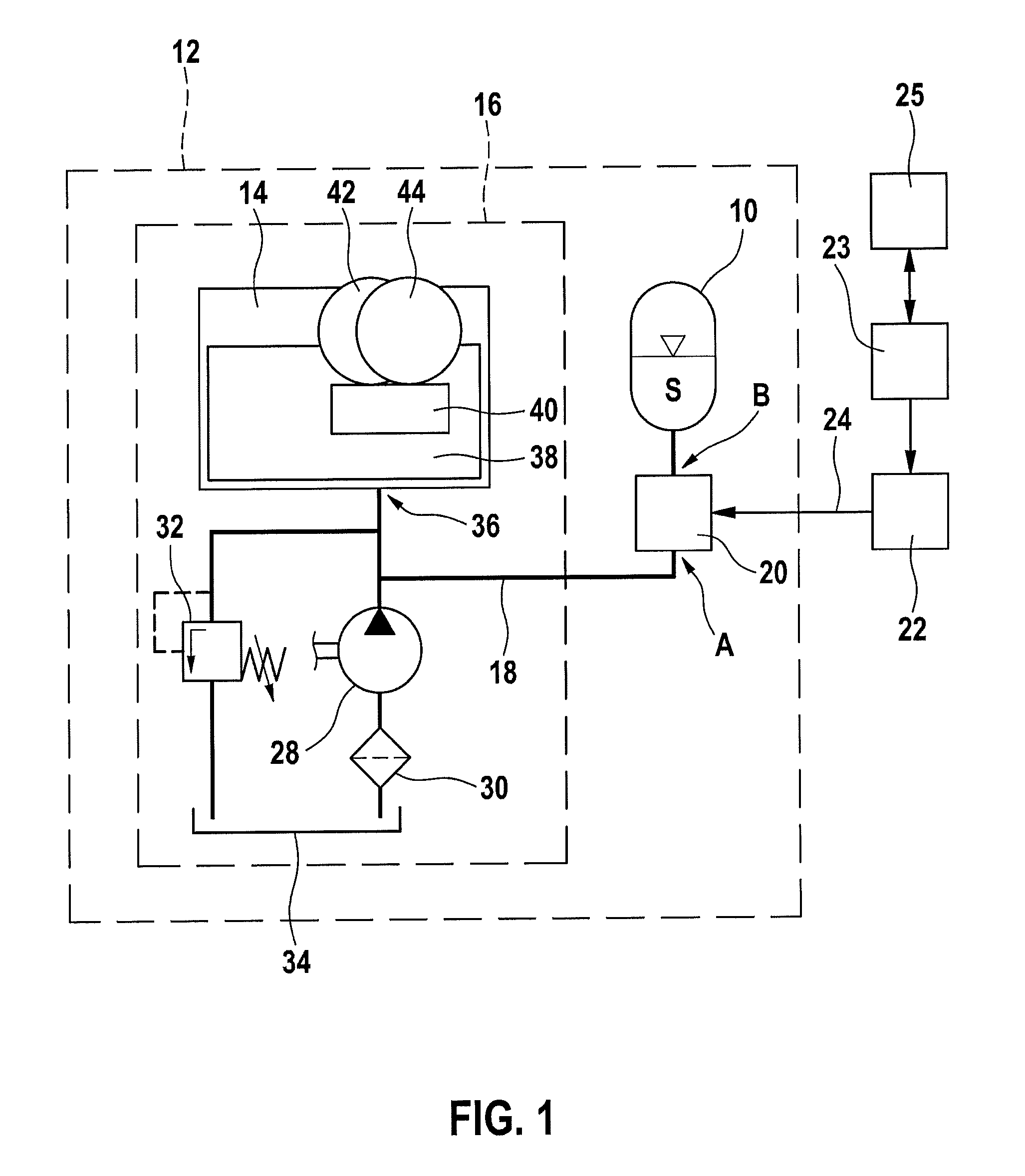
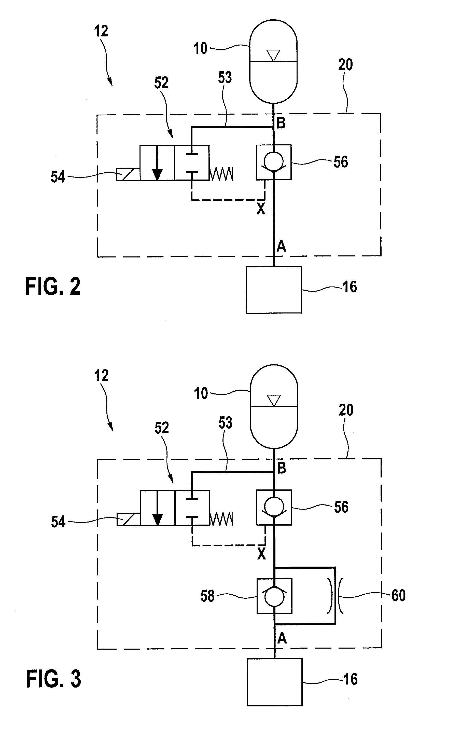
[0040]FIG. 1 shows a simplified schematic representation of a configuration of a hydraulic accumulator 10 in a hydraulic system 12 of an automatic transmission 14 of a motor vehicle, which is not illustrated in further detail herein. Hydraulic accumulator 10, which in the present case is a pressure accumulator 10, is connected to remaining hydraulic system 16 via a hydraulic connection 18 with the aid of a device 20. Device 20 is electromagnetically actuatable by a first control and / or regulating device 23 of the motor vehicle with the aid of an output stage 22. This is indicated symbolically by an arrow 24. First control and / or regulating device 23 is, for example, an engine control unit or a transmission control unit. In the present case, first control and / or regulating device 23 is also connected to a second control and / or regulating...


PUM


Abstract

A device is described for controlling a hydraulic accumulator of a hydraulic system, for example a vehicle transmission, having a valve device which may connect and disconnect an accumulator-side port of the device to and from a system-side port, the valve device including at least one first check valve which is situated hydraulically between the accumulator-side port and the system-side port, and which is blocking in the direction of the system-side port, the valve device also including an electrically actuated control valve which is situated between a control port of the first check valve and the accumulator-side port in such a way that the control valve may hydraulically unblock the first check valve, using the pressure prevailing at the accumulator-side port.

Description

FIELD[0001]The present invention relates to a device for controlling a hydraulic accumulator of a hydraulic system.BACKGROUND INFORMATION[0002]Conventional start-stop functions for motor vehicles are used with internal combustion engines to be automatically turned off by a control unit when the vehicle is at a standstill. This may help save fuel in a range from approximately 3% to approximately 5%.[0003]Automatic transmissions, for example a stepped transmission, a dual-clutch transmission or continuously variable transmissions, are generally activated hydraulically and require a hydraulic pressure and a hydraulic volumetric flow for operation. The latter is provided by a mechanical pump (i.e., one driven by the internal combustion engine), the pump generally having an overdimensioned design due to the linear dependency of the volumetric flow on the rotational speed and due to reserves provided for taking into account the idling speed of the internal combustion engine and a possibly...

Claims


Application Information

Patent Timeline
Patent Type & Authority Patents(United States)
IPC IPC(8): F16K21/04F15B1/027F16H61/00F15B13/043
CPCF15B1/027F15B13/0431F16H61/0025F16H61/0009F16H2061/0034Y10T137/794Y10T137/86485
Inventor BLOCK, RUEDIGERSTEINBACH, NILSHESS, WERNERKRASTEV, IANISLAVSCHNEIDER, HELMUTSTRAUSS, STEFFENKULOW, UWEOTT, CHRISTOF
Owner ROBERT BOSCH GMBH
Why Eureka
Try Eureka