
Apparatus and Method for Active Gap Monitoring for a Continuous Flow Machine

Inactive Publication Date: 2008-07-10
MTU AERO ENGINES GMBH
View PDF9 Cites 6 Cited by
  • Summary
  • Abstract
  • Description
  • Claims
  • Application Information

AI Technical Summary

Benefits of technology

[0011]The invention is therefore based on the objective of improving the apparatuses for active gap monitoring that were mentioned at the outset. In particular, the weight of these types of apparatuses is supposed to be reduced and homogenous cooling is supposed to be ensured.
[0012]The inventive apparatus for active gap monitoring for a continuous flow machine, in particular an aircraft propulsion device, which has a rotor and a housing which surrounds the rotor forming a rotor gap, with the apparatus

Problems solved by technology

In the case of continuous flow machines, which include, e.g., turbines, pumps, compressors or ventilators, the rotor gap between the stationary rotor housing and the rotating rotor represents a source of flow losses and therefore a cause of a decreased degree of efficiency.
The flow losses are generated firstly by the formation of turbulence and flow separation in or at the rotor gap, which also produces an increase in flow noise, and secondly, by a compensating flow, which is directed against the main flow direction by the rotor and limits the achievable pressure differential between the high pressure side and the low pressure side of the cont

Method used


Image

  • Apparatus and Method for Active Gap Monitoring for a Continuous Flow Machine
  • Apparatus and Method for Active Gap Monitoring for a Continuous Flow Machine

Examples


Example

DETAILED DESCRIPTION OF THE DRAWINGS

[0025]The following figures are schematic representations and serve to explain the invention. The same and similar components are represented by the same reference numbers. The directional indications refer to the continuous flow machine unless otherwise indicated.

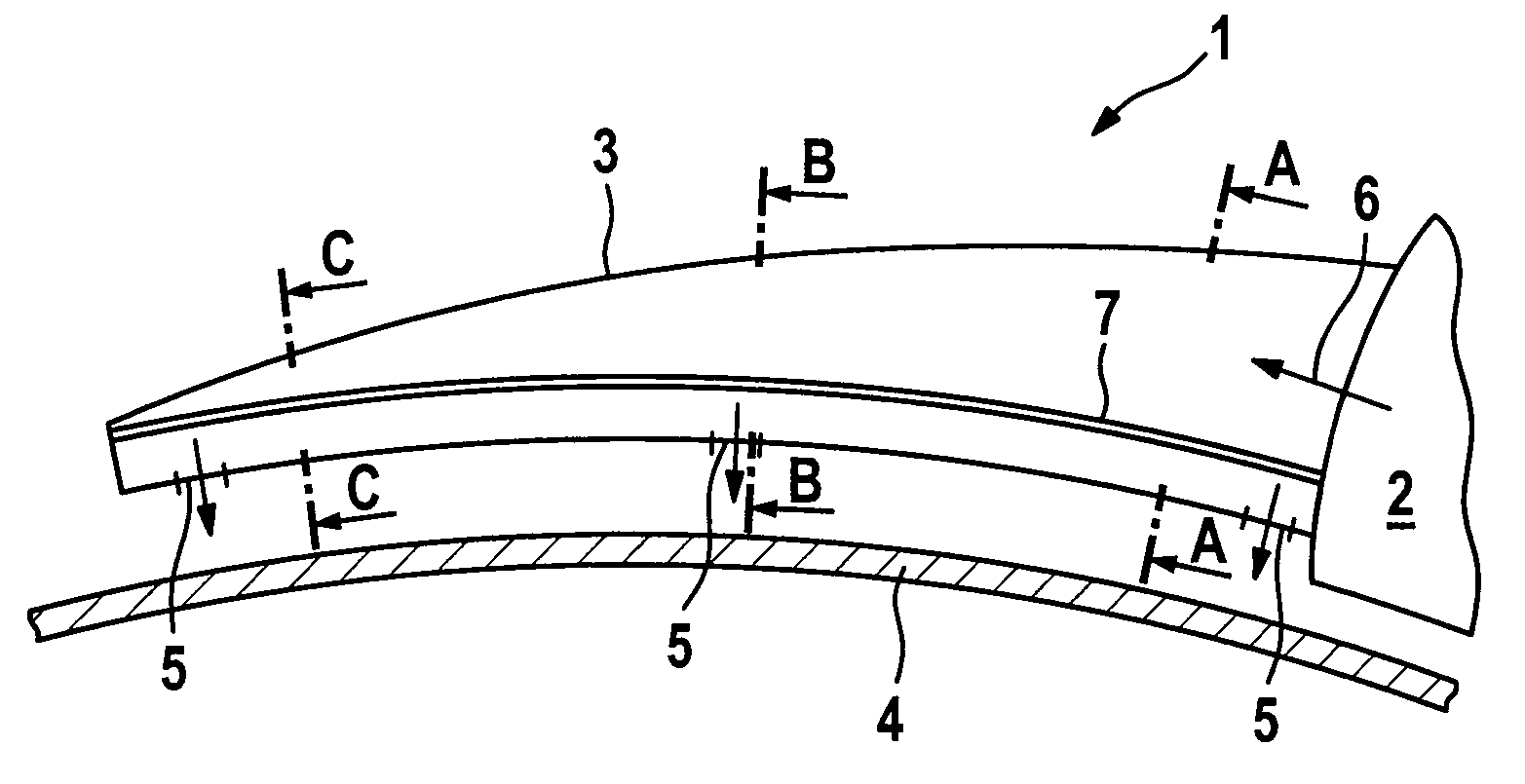
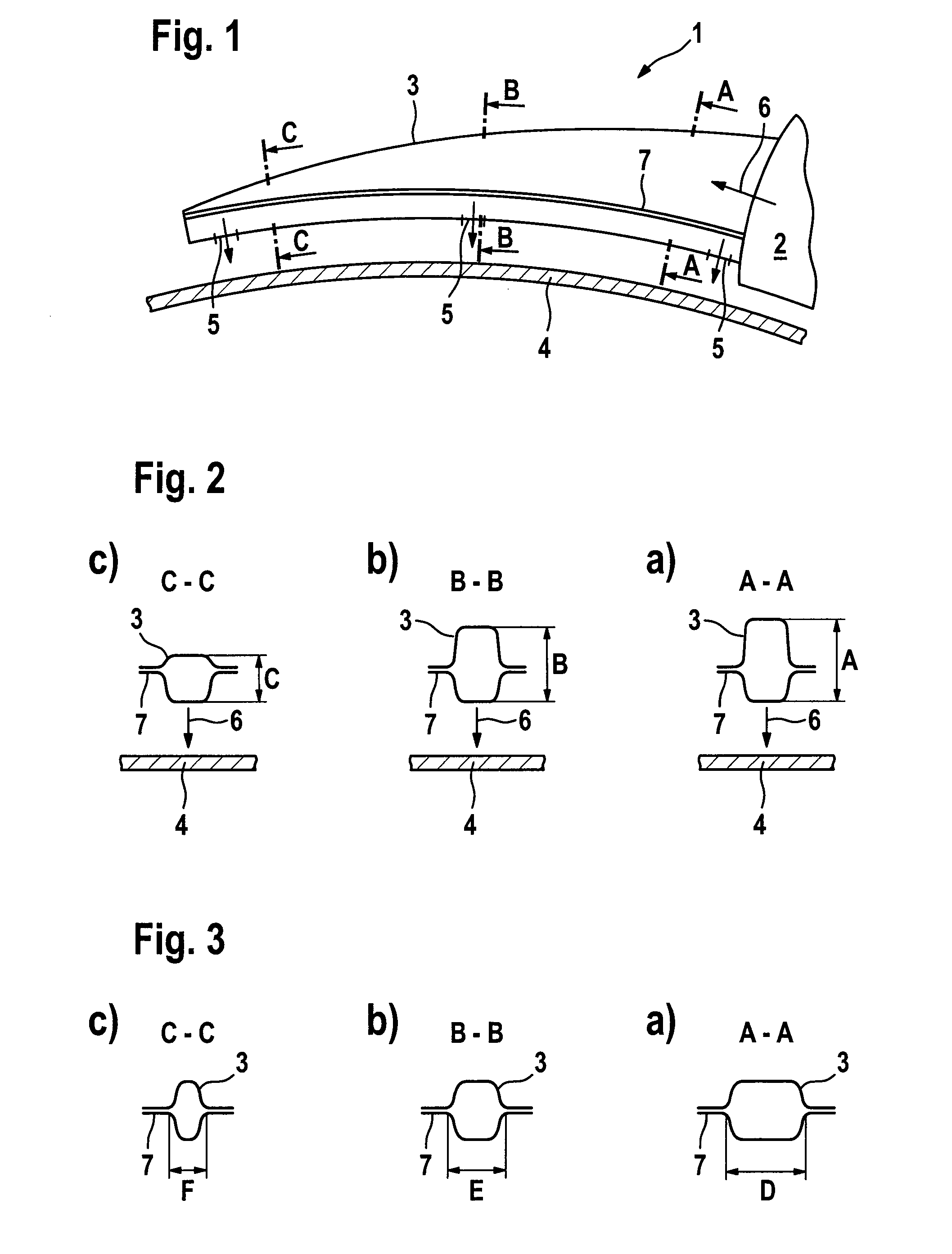
[0026]FIG. 1 shows a schematic section through a portion of an inventive apparatus for active gap monitoring 1. In this case, portions of a cooling channel 3 are depicted with a cross section that decreases over the circumference. The corresponding cross sections along Lines A-A, B-B and C-C are depicted schematically in FIGS. 2a-c.

[0027]As FIGS. 2a-c show, the cross section of the cooling channel 3 is embodied essentially rectangularly. In this case, the height, i.e., the radial extension of the cross section, decreases in the circumferential direction, i.e., in FIG. 2a the radial extension of the cross section “A” is greater than the radial extension of the cross section “B” in FIG. 2...


PUM


Abstract

An apparatus and method for active gap monitoring for a continuous flow machine, in particular an aircraft propulsion device, which has a rotor and a housing which surrounds the rotor forming a rotor gap, is disclosed. The apparatus having a cooling channel which is arranged on the external circumference of the rotor housing and is supplied with cooling air from a plenum. The cross section of the cooling channel decreases from the plenum in the circumferential direction. This ensures homogenous cooling and reduces the weight of the apparatus.

Description

[0001]This application claims the priority of International Application No. PCT / DE2006 / 001245, filed Jul. 19, 2006, and German Patent Document No. 10 2005 035 540.4, filed Jul. 29, 2005, the disclosures of which are expressly incorporated by reference herein.BACKGROUND AND SUMMARY OF THE INVENTION[0002]The invention relates to an apparatus and method for active gap monitoring for a continuous flow machine, in particular an aircraft propulsion device, which has a rotor and a housing which surrounds the rotor forming a rotor gap, with the apparatus having a cooling channel which is arranged on the external circumference of the rotor housing and is supplied with cooling air from a plenum.[0003]In the case of continuous flow machines, which include, e.g., turbines, pumps, compressors or ventilators, the rotor gap between the stationary rotor housing and the rotating rotor represents a source of flow losses and therefore a cause of a decreased degree of efficiency. The flow losses are ge...

Claims


Application Information

Patent Timeline
IPC IPC(8): F01D11/14F01D5/18
CPCF01D11/24Y02T50/671F05D2260/201F05D2250/323F05D2250/292Y02T50/676Y02T50/60
Inventor MORGENSTERN, STEFANSTANKA, RUDOLF
Owner MTU AERO ENGINES GMBH
Learn More