Blind rivet setting device

a technology of blind rivets and setting devices, which is applied in the direction of metal-working equipment, metal-working equipment, manufacturing tools, etc., can solve the problems of limited number of blind rivet fasteners to be set, limited battery energy, etc., and achieve the effect of reducing the attainable charge state and advantageous weight distribution for the technician during handling

Active Publication Date: 2015-11-26
GESIPA BLINDNIETTECHNIK GMBH
View PDF0 Cites 5 Cited by
  • Summary
  • Abstract
  • Description
  • Claims
  • Application Information

AI Technical Summary

Benefits of technology

[0018]Here, it is preferred that the ball screw comprises balls that are typically used for a 5 mm pitch. The balls are thus essentially “too large” for the ball screw. In this manner, larger mechanical loads can be accommodated.
[0019]Preferably, the housing comprises on its front face a lighting device that can be operated in at least two different modes. In addition to the “off” mode, a “constant light” mode and a “process light” mode can be used, for example. In the “constant light” mode, a type of flashlight effect is produced. In the “process light” mode, a beam of light is directed at the blind rivet fastener that is being set during the setting operation.
[0020]Preferably, the battery is a rechargeable battery and comprises a first encoding for the blind rivet setting device and a second encoding for a charging device. The encoding can be embodied in a mechanical, electrical, optical or other manner. By the double encoding, it is ensured that, not only will the battery be used with the correct blind rivet setting device, but the battery will only be charged by the correct charging device. The risk of the durability of the battery being impaired by improper handling and the attainable charge state being reduced is thus small.
[0021]Preferably, the battery is connected to the housing by a sliding connection. In the case of known blind rivet setting devices, the battery is inserted into the handle piece of the housing from below. During operation, the battery is then located at the bottom in the direction of gravity, and there exists the danger of the battery falling out of the housing and injuring the technician or of the battery simply being lost, for example, at construction sites. With a sliding connection, the battery can still be arranged at the bottom end of the housing, which results in an advantageous weight distribution for the technician during handling. However, in this position, it is placed onto the housing perpendicular to the direction of gravity and is then connected to the housing by means of the sliding connection.
[0022]It is also advantageous if the battery is secured in the housing by at least two mechanical locks that are arranged one after another in the sliding direction. This reduces the risk of the battery falling out of the housing and being able to cause injuries or damage.

Problems solved by technology

However, an embodiment of this type has the disadvantage that the battery only holds a limited supply of energy and that the number of blind rivet fasteners that are to be set is therefore limited.

Method used


Image

  • Blind rivet setting device
  • Blind rivet setting device
  • Blind rivet setting device

Examples


Embodiment Construction

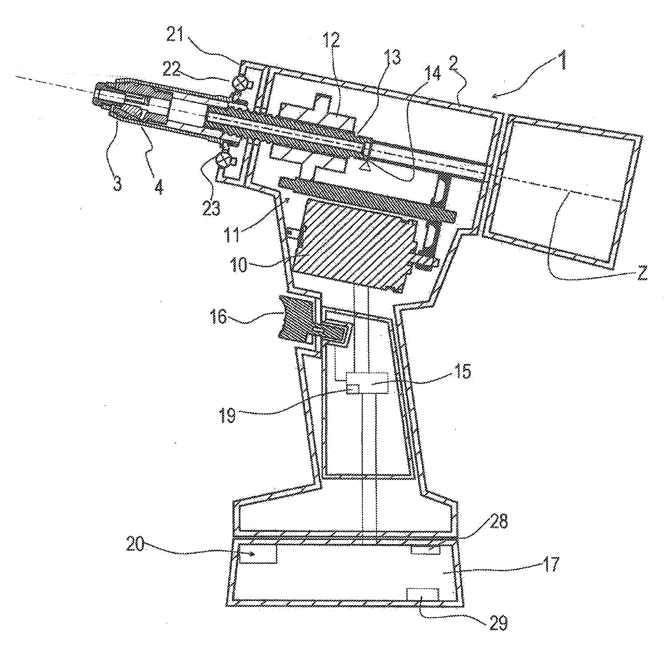
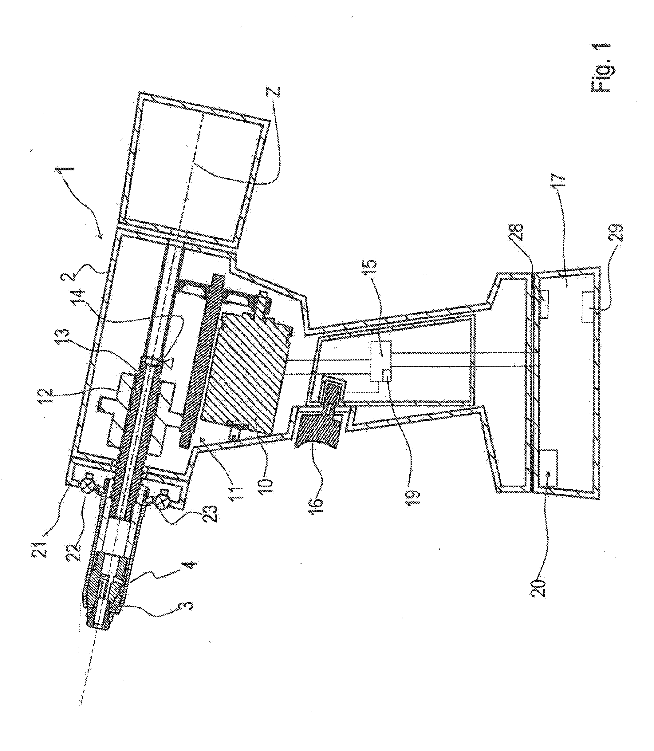
[0008]Embodiments of the invention are directed to a blind rivet setting device with which a largest possible number of blind rivet fasteners can be set.

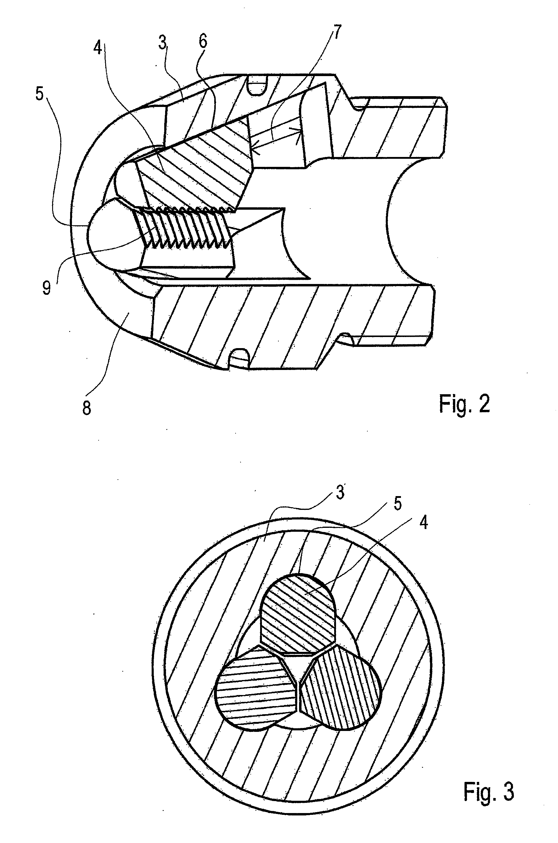
[0009]Accordingly, a blind rivet setting device of the type named at the outset includes chuck housing that includes, for each clamping jaw, a guide path with a path base slanted against the pulling direction. Further, each clamping jaw bears against a respective path base so that its back lies flat against the path base over the clamping distance. A spring is provided which applies a force to the clamping jaws into the chuck housing.

[0010]Thus, not only are the clamping jaws guided in an inner cone, against which they bear virtually with only one line, but the clamping jaws are also guided in a type of channel, so that the force which the chuck housing applies radially inwards to the clamping jaws can be introduced into the clamping jaws over a larger area. Furthermore, the guide paths prevent a lateral deviation of the clamping ja...


PUM

PropertyMeasurementUnit
pulling distanceaaaaaaaaaa
distanceaaaaaaaaaa
clamping distanceaaaaaaaaaa

Abstract

A blind rivet setting device and method of setting a blind rivet. The device includes a housing; a pulling mechanism, arranged in the housing, that includes a chuck housing movable in a pulling direction and clamping jaws movable along a clamping distance in the chuck housing; an electric drive, structured and arranged to act on the chuck housing, that includes a control device; an electric battery structured and arranged as an energy source for the electric drive; and a spring structured and arranged in the chuck housing to apply a force to clamping jaws. For each clamping jaw, the chuck housing includes a guide path with a path base obliquely oriented to the pulling direction, and a back of each clamping jaw is supported against its respective path base over the clamping distance.

Description

CROSS-REFERENCE TO RELATED APPLICATIONS[0001]The present application claims priority under 35 U.S.C. §119 of European Patent Application No. 14 156 307.2, filed Feb. 24, 2014, the disclosure of which is expressly incorporated by reference herein in its entirety.BACKGROUND OF THE INVENTION[0002]1. Field of the Invention[0003]Embodiments of the invention relate to a blind rivet setting device having a housing, a pulling mechanism in the housing, which comprises a chuck housing that can be moved in a pulling direction and clamping jaws that can be moved along a clamping distance in the chuck housing, an electric drive, which acts on the chuck housing and comprises a control device, and an electric battery as an energy source for the drive.[0004]2. Discussion of Background Information[0005]A blind rivet setting device of this type is, for example, known from DE 41 26 602 A1.[0006]“Blind rivet setting device” is to be understood below as meaning a device that can be used to set blind riv...

Claims


Application Information

Patent Timeline
Patent Type & Authority Applications(United States)
IPC IPC(8): B21J15/10B21J15/26B21J15/04
CPCB21J15/105B21J15/043Y10T29/53752Y10T29/49957B21J15/26B21J15/326B25B27/0014
Inventor GAERTNER, RICHARDWILLE, LOTHARLEINWEBER, MICHAELSCHOENBERNER, ALEX
Owner GESIPA BLINDNIETTECHNIK GMBH
Why Eureka
Try Eureka