Band clamp

a technology of a band clamp and a sleeve, which is applied in the direction of hose connections, machine supports, other domestic objects, etc., can solve the problems of not being able to be temporarily applied to an elongated object while in the open position, and not being strong enough to grasp the object to be retained on the elongated obj

Active Publication Date: 2007-10-23
HEYCO
View PDF8 Cites 33 Cited by
  • Summary
  • Abstract
  • Description
  • Claims
  • Application Information

AI Technical Summary

Benefits of technology

[0005]The clamp, when installed on an elongated object (e.g., a hose) in its radially expanded position, can be properly positioned relative to the end of the elongated object so as to frictionally grip the elongated object tightly enough to retain the clamp in a selected position yet not so tight that the clamp's position cannot be adjusted. This allows the clamp to be assembled to, for instance, a while the clamp is disengaged. After shipping the resulting assembly to a jobsite, the clamp can be repositioned without removing it from the hose and then engaged to attach the hose to a mating structure, such as a mechanical fitting or the like, thereby facilitating both transportation and installation of the clamp.

Problems solved by technology

The prior art hose clamps, e.g., like those described in the Yu '501 Patent, cannot grasp the object strongly enough to be retained on the elongated object without closing the clamp.
As a result, they are not capable of being temporarily applied to an elongated object while in their open position (e.g., for transportation to a job site prior to actual installation).

Method used


Image

  • Band clamp
  • Band clamp
  • Band clamp

Examples


Embodiment Construction

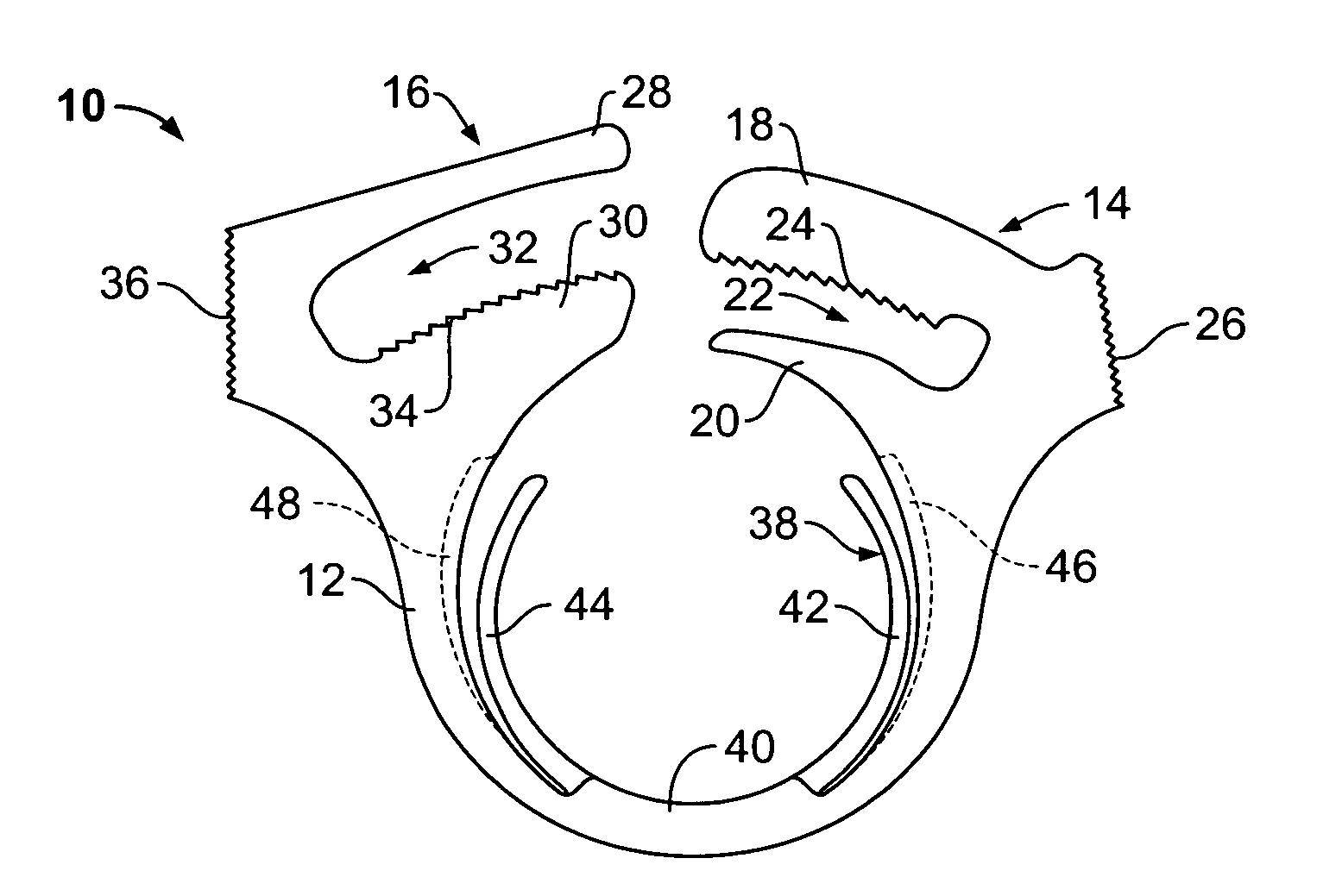
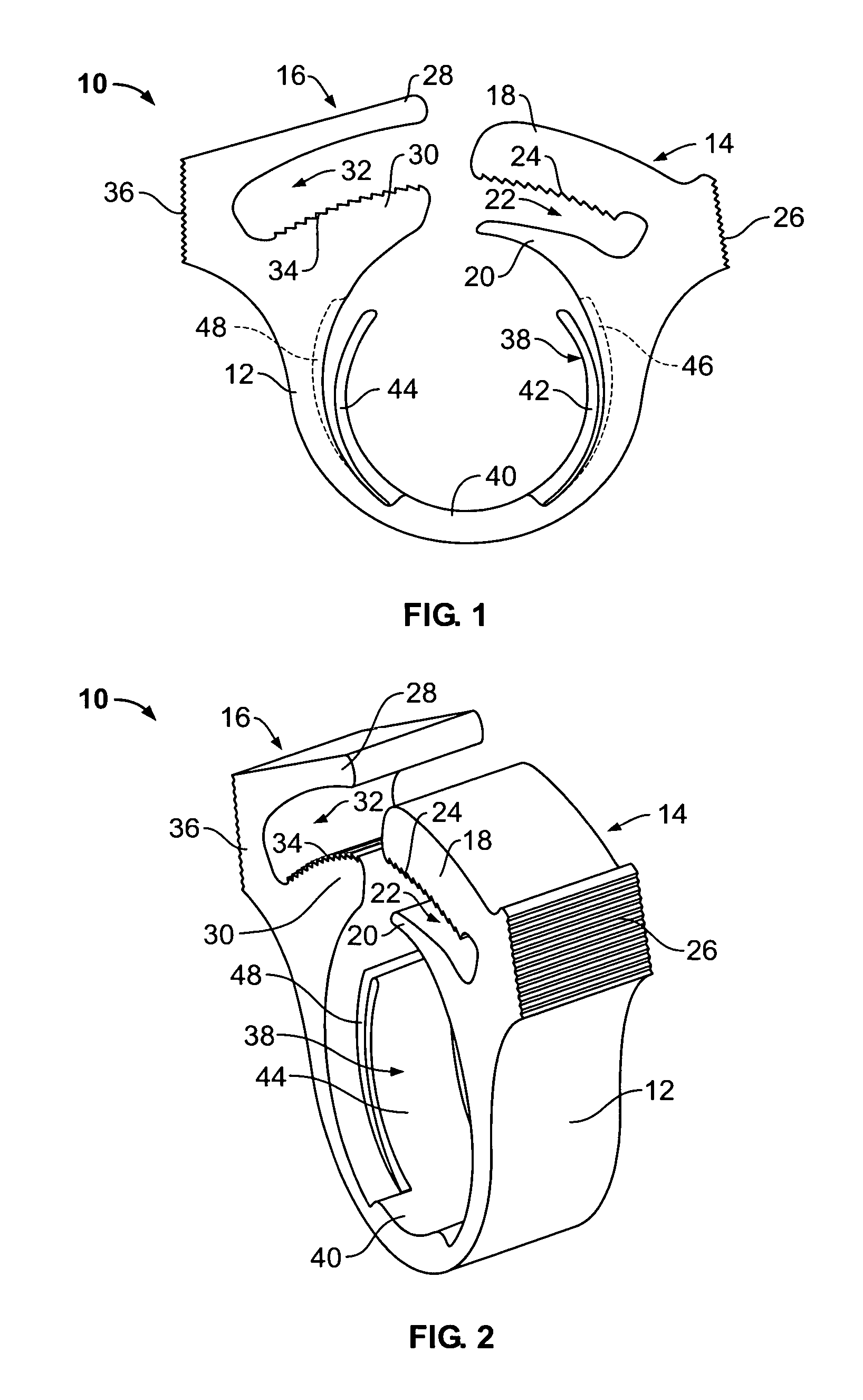
[0014]Although the present invention can be used in conjunction with any type of hose, conduit, wire bundle, or the like, it is particularly suitable for use as a hose fitting. Accordingly, the present invention will be described hereinafter as such. It should be understood, however, that the following description is only meant to be illustrative of the present invention and is not meant to limit the scope of the present invention, which has applicability for grasping and / or clamping other types of elongated objects.

[0015]With reference to FIGS. 1 and 2, a band clamp 10, preferably made of a plastic, such as nylon, and manufactured via injection molding, includes an outer band 12 in the form of an open-ended loop and having complementary, interlocking closure members 14, 16 provided at adjacent ends of the outer band 12. The closure member 14 has an upper tongue 18 and a lower jaw 20 which cooperate with each other to form an elongated, open-ended cavity 22 therebetween. The closure...


PUM


Abstract

A band clamp can be movably applied to an elongated object, such as a hose, conduit or the like, when the band clamp is in an open or non-engaged position. In one embodiment, the elongated object is gripped between a pair of arms which project inwardly from opposite sides of an inner circumferential surface of the band when the band is in its open or non-engaged position. The inner circumferential surface of the band also includes a pair of recesses, one on each side thereof. When the band is in its closed or engaged position, each of the arms is received in a corresponding recess. The first and second arms are attached at a common junction with the band forming an arc that is no less than about 180°.

Description

FIELD OF THE INVENTION [0001]The present invention relates to band clamps and, more particularly, to a band clamp for grasping an elongated object along the length thereof, e.g., for securing a hose to a nipple-type fitting.BACKGROUND OF THE INVENTION [0002]Band clamps for grasping and / or compressing an elongated object, such as a conduit, wire bundle, or hose are known in the art. One common type of band clamp is disclosed in U.S. Pat. No. 5,423,501 to Yu, which discloses a generally annular open-ended band, the free ends of which have interlocking elements. After the band clamp is properly positioned on a conduit, the free ends are urged together whereupon the band clamp constricts about the conduit and the interlocking elements become engaged to prevent the band clamp from loosening.[0003]The prior art hose clamps, e.g., like those described in the Yu '501 Patent, cannot grasp the object strongly enough to be retained on the elongated object without closing the clamp. As a result...

Claims


Application Information

Patent Timeline
Patent Type & Authority Patents(United States)
IPC IPC(8): F16L33/00F16L33/035F16L33/02
CPCF16L33/035Y10T24/1498Y10T24/1482
Inventor LARES, JOSEPH G.
Owner HEYCO
Why Eureka
Try Eureka