Methods and apparatus for optimum packet aggregation in a communication network

a communication network and packet aggregation technology, applied in electrical equipment, digital transmission, data switching networks, etc., can solve the problems of increasing processor occupancy and extra processing power, and achieve the effect of optimizing resource utilization and improving packet transport efficiency

Active Publication Date: 2007-10-23
LUCENT TECH INC +1
View PDF9 Cites 9 Cited by
  • Summary
  • Abstract
  • Description
  • Claims
  • Application Information

AI Technical Summary

Benefits of technology

[0007]The present invention is a method and apparatus to aggregate or bundle packets to optimize the resource utilization and improve the transport efficiency of packets which are transferred between various protocol layers in a communications network. One embodiment of the invention sets forth a method of aggregating packets of a first size to packets of a second size for transmission in a wireless communications network between, for example, a base station controller and base transmitting station. The method includes the steps of calculating a maximum bundling factor represented by (an IP packet MTU size at a first location minus protocol overhead) divided by an application layer packet size and determining a most efficient bundling factor in terms of packet fragments, where the most efficient bundling factor is determined by a largest packet per fragment ratio. If the number of packets to be bundled is less than or equal to the maximum bundling factor then all packets are bundled together for a next step in the transmission. If the number of packets to be bundled is greater than the maximum bundling factor, then packets are bundled according to the most efficient bundling factor for the next step in the transmission. If there are multiple bundling factors having a same bundling efficiency, a larger of the multiple bundling factors having the same bundling efficiency is selected as the most efficient bundling factor.

Problems solved by technology

Fragmentation at the CRC requires extra processing power and increases the processor occupancy.

Method used


Image

  • Methods and apparatus for optimum packet aggregation in a communication network
  • Methods and apparatus for optimum packet aggregation in a communication network
  • Methods and apparatus for optimum packet aggregation in a communication network

Examples


Embodiment Construction

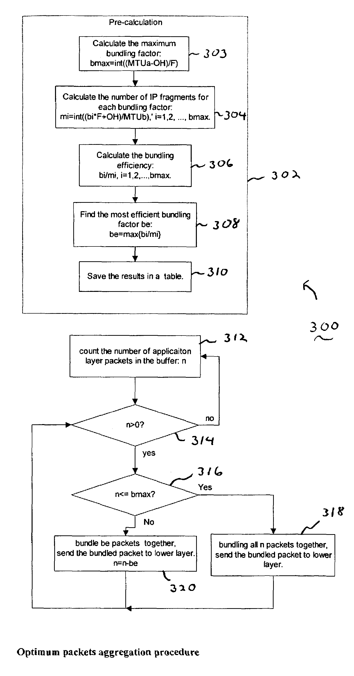
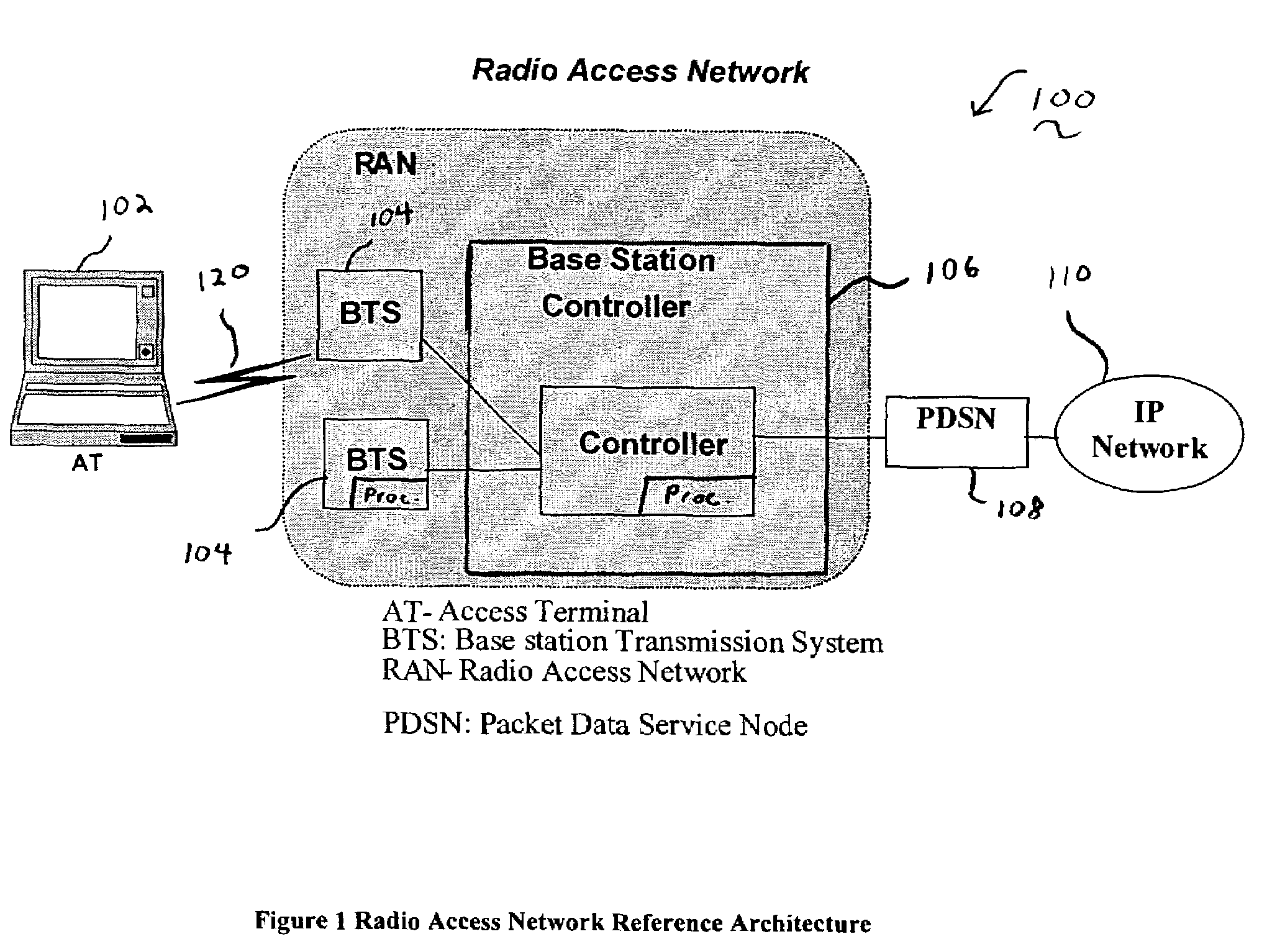
[0013]The present invention is a methodology for providing packet aggregation to achieve optimum trade-off between transport efficiency and processing power. Although an exemplary embodiment of the invention is described in connection with the transmission between a base station controller (BSC) and cell radio control unit (CRC) at a base station (BTS), and the CRC to the modem cards in BTS, and the interface / link between them, it would be apparent to those skilled in the art that the present invention is applicable to other network areas requiring packet aggregation, including, for example, voice over IP networks where small application layer packets (e.g., voice frames) need to be aggregated or multiplexed together to be transported over IP networks.

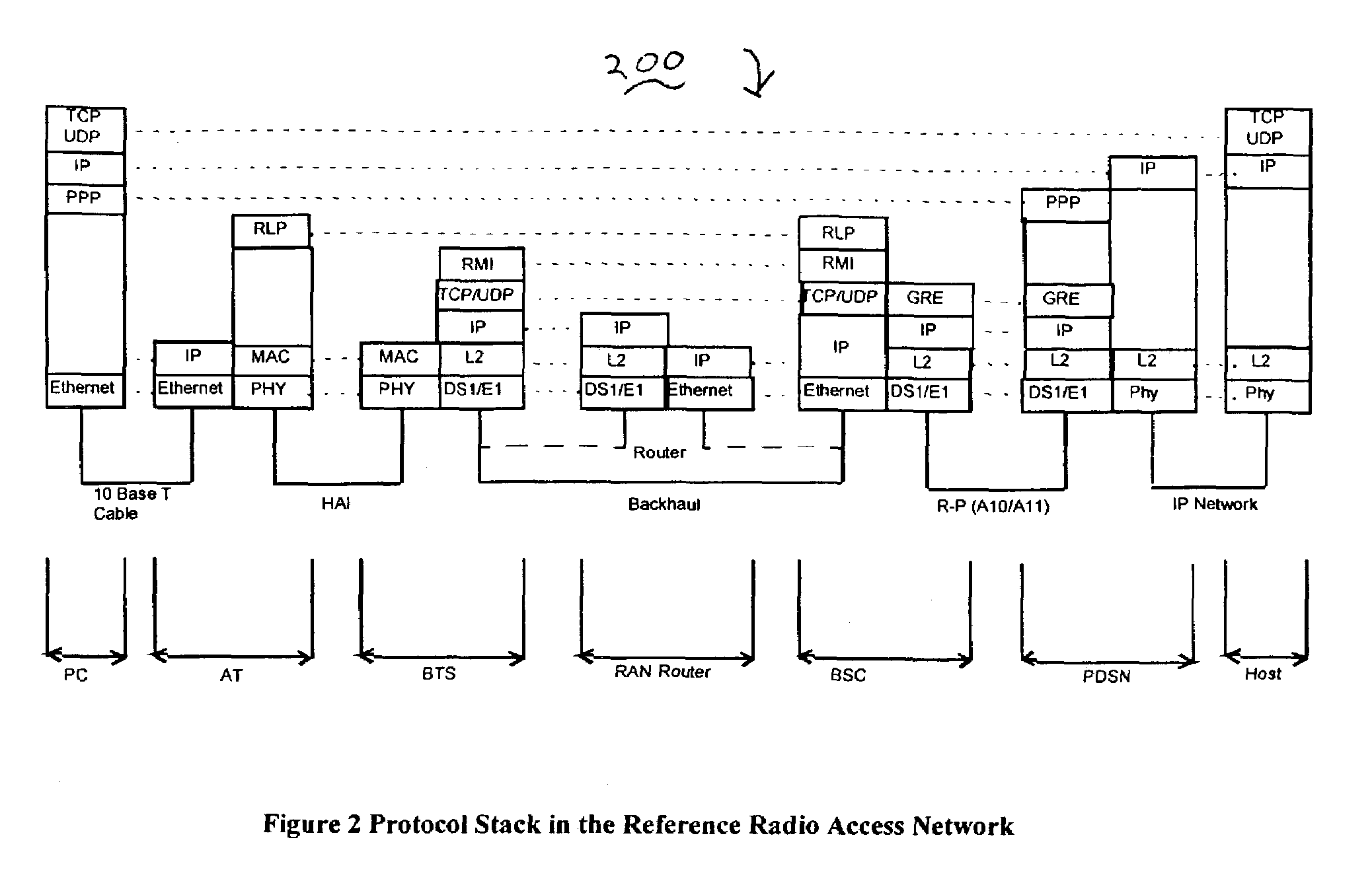
[0014]In accordance with the discussion of the present invention, it is assumed that application layer packets (e.g., the RLP frames) can be aggregated and encapsulated into an IP packet (executed via multiple layers in the example) at...


PUM


Abstract

The present invention is a method and apparatus to aggregate or bundle packets to optimize the resource utilization and improve the transport efficiency of packets which are transferred between various protocol layers in a communications network. One embodiment of the invention sets forth a method of aggregating packets of a first size to packets of a second size for transmission in a wireless communications network between, for example, a base station controller and base transmitting station. The method includes the steps of calculating a maximum bundling factor represented by (an IP packet MTU size at a first location minus protocol overhead) divided by an application layer packet size and determining a most efficient bundling factor in terms of packet fragments, where the most efficient bundling factor is determined by a largest packet per fragment ratio. If the number of packets to be bundled is less than or equal to the maximum bundling factor then all packets are bundled together for a next step in the transmission. If the number of packets to be bundled is greater than the maximum bundling factor, then packets are bundled according to the most efficient bundling factor for the next step in the transmission. If there are multiple bundling factors having a same bundling efficiency, a larger of the multiple bundling factors having the same bundling efficiency is selected as the most efficient bundling factor.

Description

FIELD OF THE INVENTION[0001]The present invention relates generally to packet communications networks and more particularly to packet aggregation and / or multiplexing techniques within such networks.BACKGROUND OF THE INVENTION[0002]Referring to FIG. 1, an exemplary network 100 including multiple nodes is shown. The exemplary network 100 may be, for example, a radio access network for high speed wireless data applications. Typical radio access networks, like that shown in FIG. 1 include one or more Access Terminals 102 (AT), Base Stations 104 (BTS), and Base Station Controllers 106 (BSC). A PDSN 108 interfaces between the IP network and the radio access network. The BSC 106 receives data from the core network 110 and passes the data to the BTS 104 so that the BTS can transmit the data to the AT 102 over the wireless link 120. Data is communicated through the reverse direction as well and passed from AT 102 to the core network 110. In general, each node consists of multiple functional ...

Claims


Application Information

Patent Timeline
Patent Type & Authority Patents(United States)
IPC IPC(8): H04J3/16H04J3/22H04L12/56
CPCH04L47/10H04L47/36H04W92/12H04L2212/0025H04L2212/00
Inventor SAMADI, BEHROKHZHANG, QINQING
Owner LUCENT TECH INC
Why Eureka
Try Eureka