Supercharge Your Innovation With Domain-Expert AI Agents!

Exhaust after-treatment system with in-cylinder addition of unburnt hydrocarbons

a technology of exhaust after-treatment and hydrocarbons, which is applied in the direction of mechanical equipment, machines/engines, electric control, etc., can solve the problems of incompatibility of fuel injectors in typical engine cylinders, engine malfunctions, and increased cost and complexity of exhaust after-treatment systems

Active Publication Date: 2007-10-30
CATERPILLAR INC
View PDF11 Cites 5 Cited by
  • Summary
  • Abstract
  • Description
  • Claims
  • Application Information

AI Technical Summary

Problems solved by technology

Although the injection of the fuel creates the reductant-rich exhaust and the elevated exhaust temperatures needed for regeneration, the additional fuel injector increases the cost and complexity of the exhaust after-treatment system.
Moreover, it has been found that typical engine cylinder fuel injectors are incompatible with injecting the additional fuel into the exhaust prior to expelling the exhaust from the combustion chamber.
The fuel can then dilute the lubricating oil, leading to engine malfunctions, such as piston seizure.

Method used


Image

  • Exhaust after-treatment system with in-cylinder addition of unburnt hydrocarbons
  • Exhaust after-treatment system with in-cylinder addition of unburnt hydrocarbons
  • Exhaust after-treatment system with in-cylinder addition of unburnt hydrocarbons

Examples


first embodiment

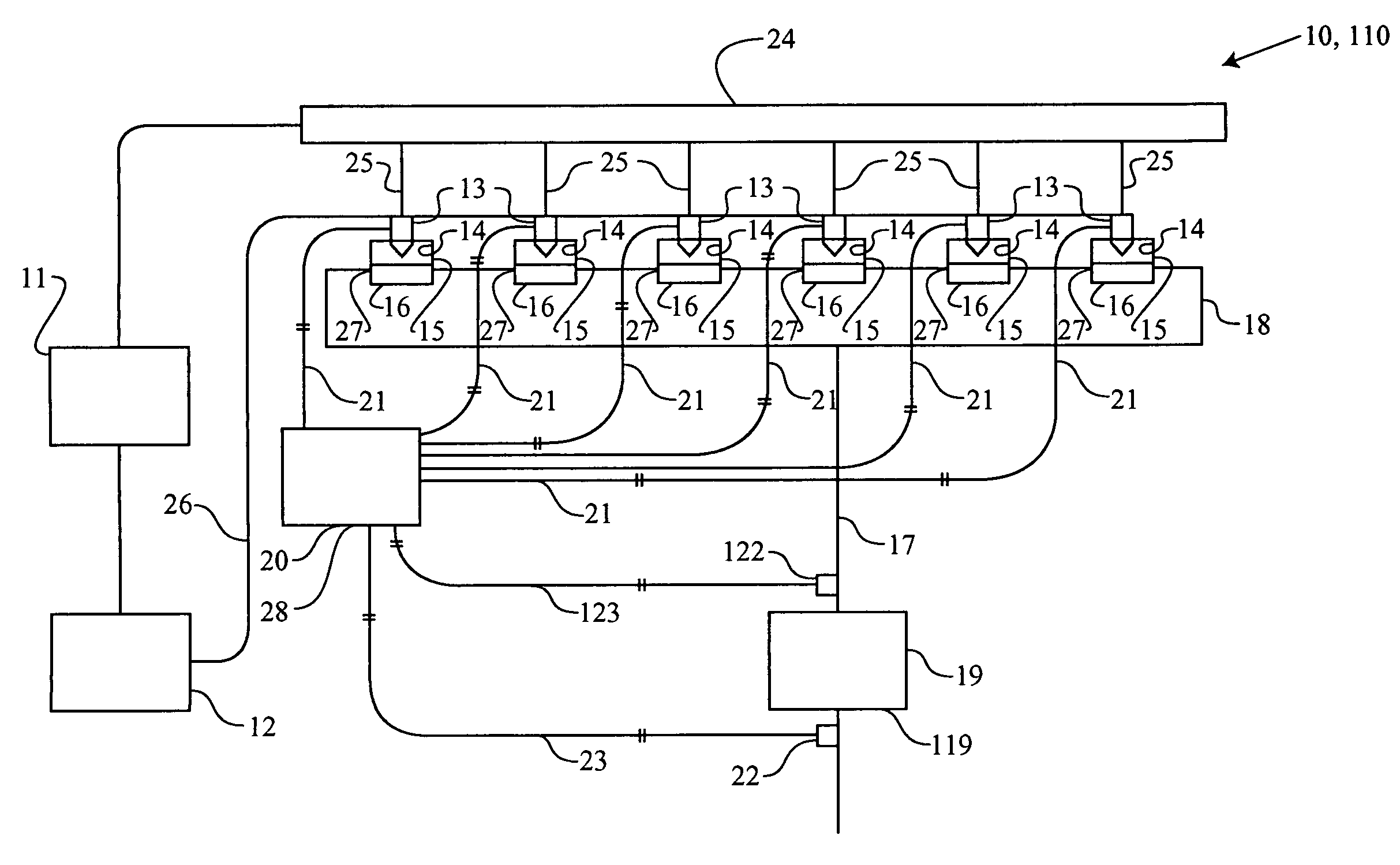
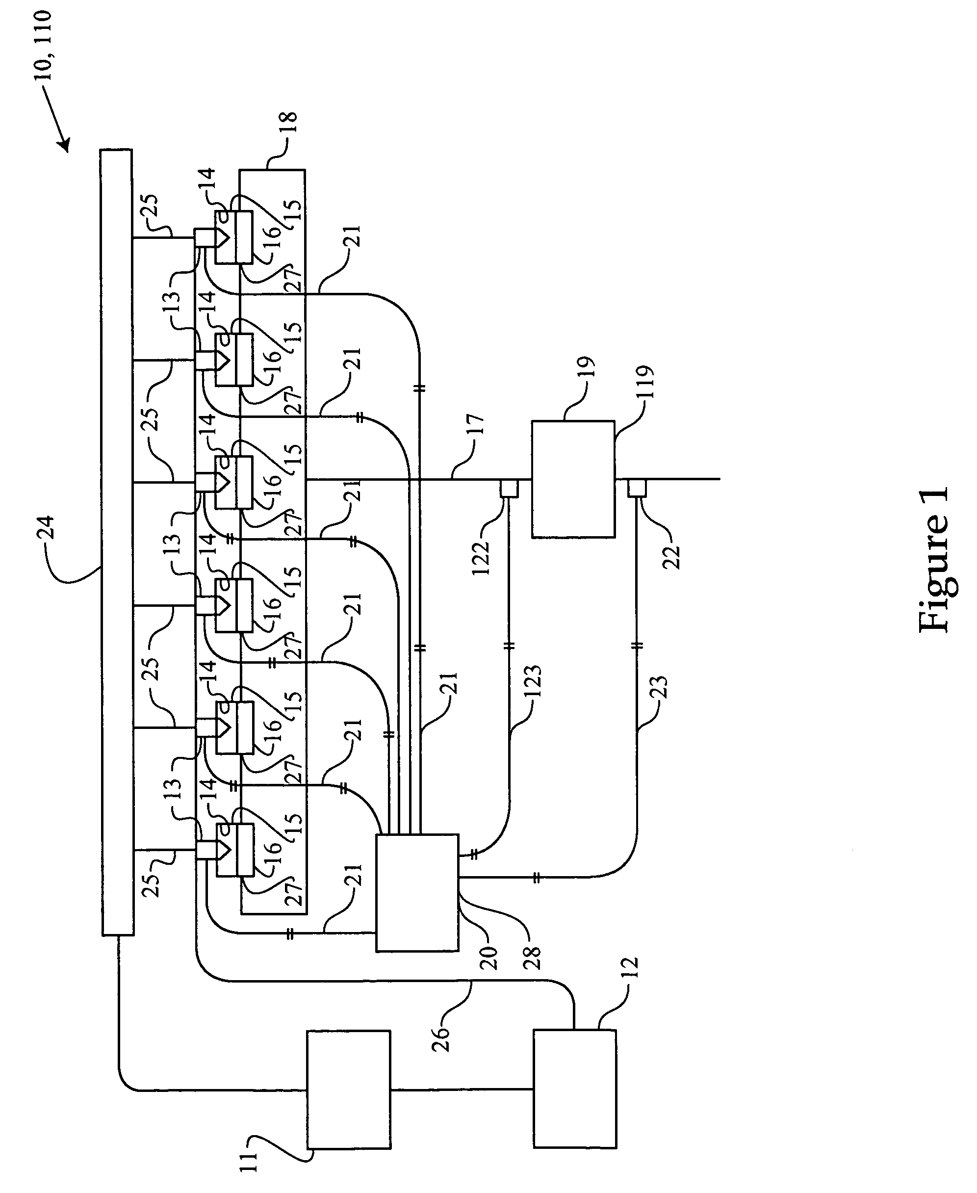
[0021] an article 28 includes a computer readable storage medium on which a regeneration algorithm is stored. The article 28 includes the electronic control module 20. The regeneration algorithm is operable to signal each fuel injector 13 to inject an additional amount of fuel in the first spray pattern 52 during at least one of the expansion stroke and the exhaust stroke of at least one engine cycle within the regeneration phase of the NOx adsorber 19. Because the additional amount of fuel is being injected during the exhaust or expansion stroke, the combustion chamber 14 is in a non-combustible environment and the additional amount of fuel will be unburnt when moved into the exhaust passage 17. The unburnt fuel will create the reductant-rich conditions needed for regeneration of the NOx adsorber 19. The regeneration algorithm includes a determining algorithm operable to determine when the regeneration phase of the NOx adsorber 19 begins and ends. Although the determining algorithm...

third embodiment

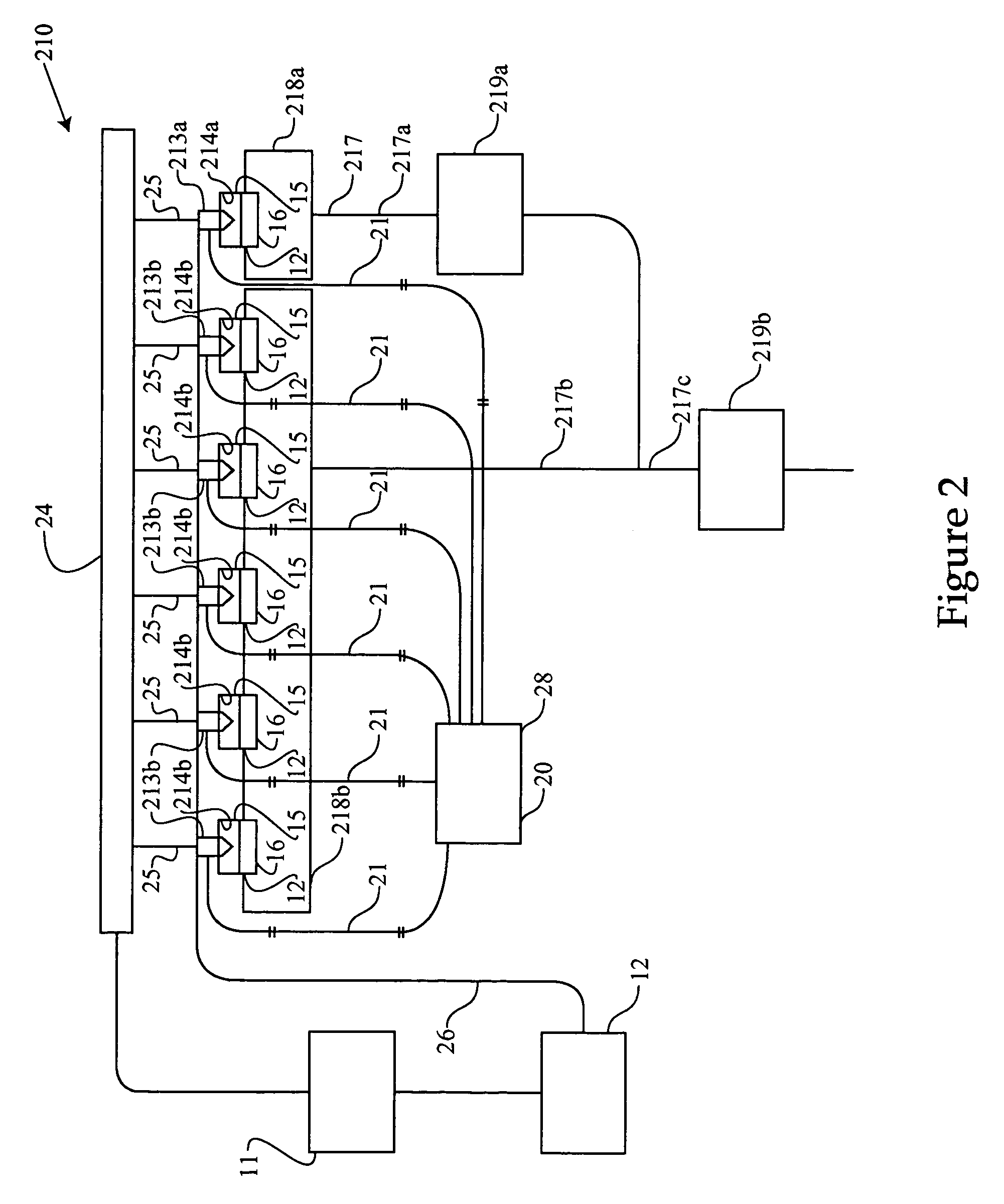
[0026]Referring to FIG. 2, there is shown a schematic representation of an exhaust after-treatment system 210, according to the present disclosure. A first exhaust manifold 218a fluidly connects one of the combustion chambers, referred to as a first combustion chamber 14a, with a first section 17a of the exhaust passage 17. A second exhaust manifold 218b fluidly connects a second portion of the combustion chambers 14b, illustrated as five combustion chambers, with a second section 17b of the exhaust passage 17. The first and second sections 17a and 17b of the exhaust passage 17 merge to form a merged section 17c of the exhaust passage 17. It should be appreciated that any number of combustion chambers could be fluidly connected to the first exhaust manifold and the second exhaust manifold depending on the desired power output and other known considerations. The plurality of fuel injectors 213 are divided into a first group, being a first fuel injector 213a operable to inject fuel in...


PUM


Abstract

Certain exhaust after-treatment devices, at least periodically, require the addition of unburnt hydrocarbons in order to create reductant-rich exhaust conditions. The present disclosure adds unburnt hydrocarbons to exhaust from at least one combustion chamber by positioning, at least partially within a combustion chamber, a mixed-mode fuel injector operable to inject fuel into the combustion chamber in a first spray pattern with a small average angle relative to a centerline of the combustion chamber and a second spray pattern with a large average angle relative to the centerline of the combustion chamber. An amount of fuel is injected in the first spray pattern into a non-combustible environment within the at least one combustion chamber during at least one of an expansion stroke and exhaust stroke. The exhaust with the unburnt amount of fuel is moved into an exhaust passage via an exhaust valve.

Description

U.S. GOVERNMENT RIGHTS[0001]This disclosure was made with government support under the terms of Contract No. DE-FC05-97OR22605 awarded by the Department of Energy. The government may have certain rights in this invention.TECHNICAL FIELD[0002]The present disclosure relates generally to exhaust after-treatment systems, and more specifically to a method of adding unburnt hydrocarbons to the exhaust in after-treatment systems.BACKGROUND[0003]Certain diesel engine exhaust after-treatment systems require an addition of reductants, such as hydrocarbons, and / or elevated exhaust temperatures to chemically purge material that has been stored in an exhaust after-treatment device. For instance, a NOx adsorber catalytic converter, often referred to as a NOx trap, operates in two alternative phases: a storage phase and a regeneration phase. During the storage phase, the normal operation of an engine produces a reductant-lean exhaust in which the NOx is oxidized and stored on the NOx adsorber. Dur...

Claims


Application Information

Patent Timeline
Patent Type & Authority Patents(United States)
IPC IPC(8): F01N3/00F01N3/02
CPCF02D41/027F02M45/086F02M61/1813F02M61/182F02D41/405F01N3/023F01N3/0871F01N2430/085F02D41/047F02M2200/46Y02T10/44Y02T10/40
Inventor COLEMAN, GERALD N.KESSE, MARY L.
Owner CATERPILLAR INC
Features
  • R&D
  • Intellectual Property
  • Life Sciences
  • Materials
  • Tech Scout
  • Unparalleled Data Quality
  • Higher Quality Content
  • 60% Fewer Hallucinations
Learn More