Disposition introduced to hydropneumatic jack

a technology of hydropneumatic jack and jack body, which is applied in the direction of lifting frames, lifting devices, vehicle maintenance, etc., can solve the problems of loss of pressure and increased expenses, and achieve the effects of reducing maintenance costs, improving operation, and reducing costs

Inactive Publication Date: 2007-11-06
KEKO ACESSORIOS
View PDF10 Cites 22 Cited by
  • Summary
  • Abstract
  • Description
  • Claims
  • Application Information

AI Technical Summary

Problems solved by technology

Therefore, this object was developed from difficulties that were already present in previous models, mainly for those that referred to operating time, maintenance of the elements of the set, and the manufacturing difficulty which consequently means more expenses.
This function was performed directly by the continuous pneumatic pump, which resulted in loss of pressure.

Method used


Image

  • Disposition introduced to hydropneumatic jack
  • Disposition introduced to hydropneumatic jack
  • Disposition introduced to hydropneumatic jack

Examples


Embodiment Construction

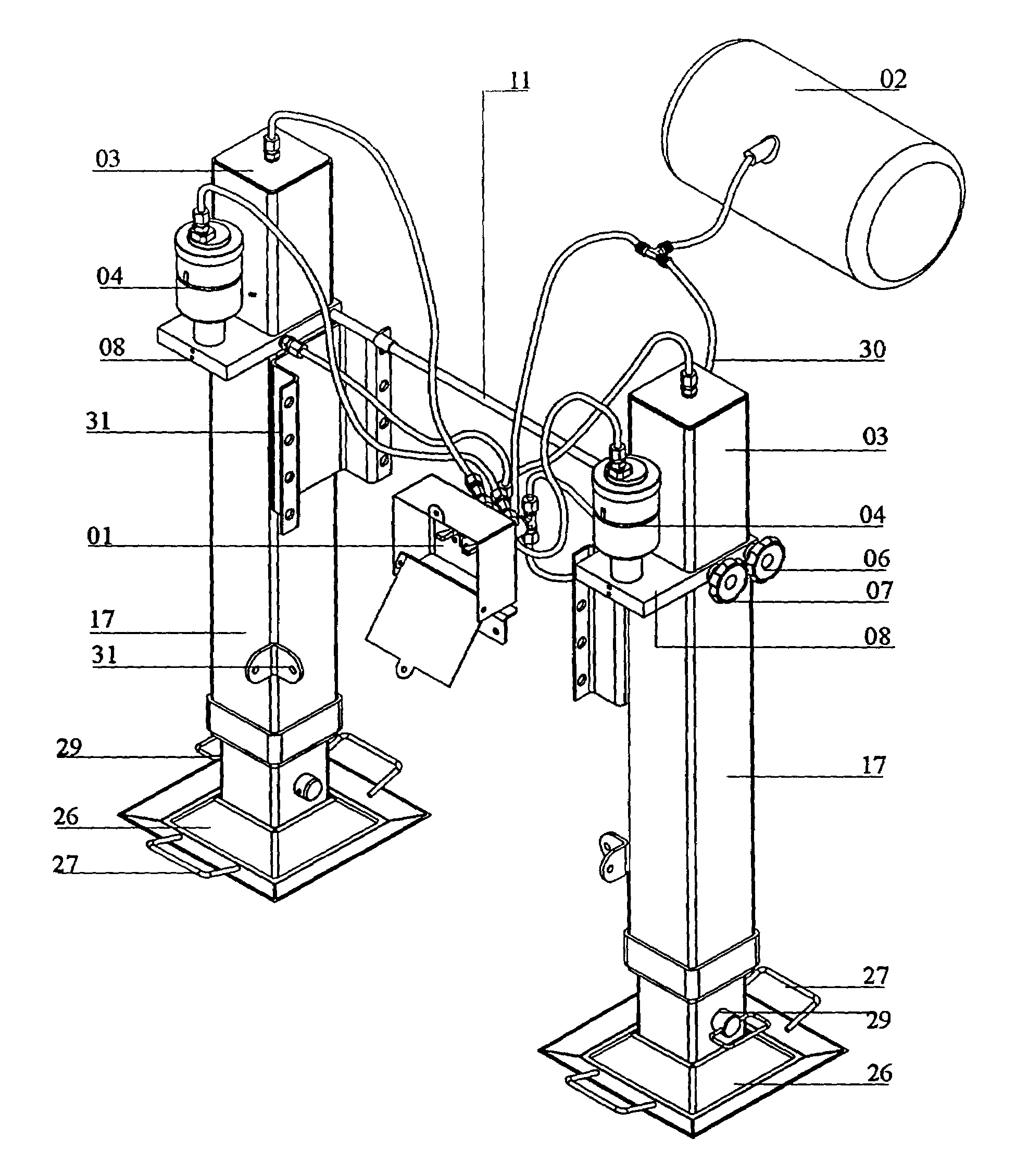
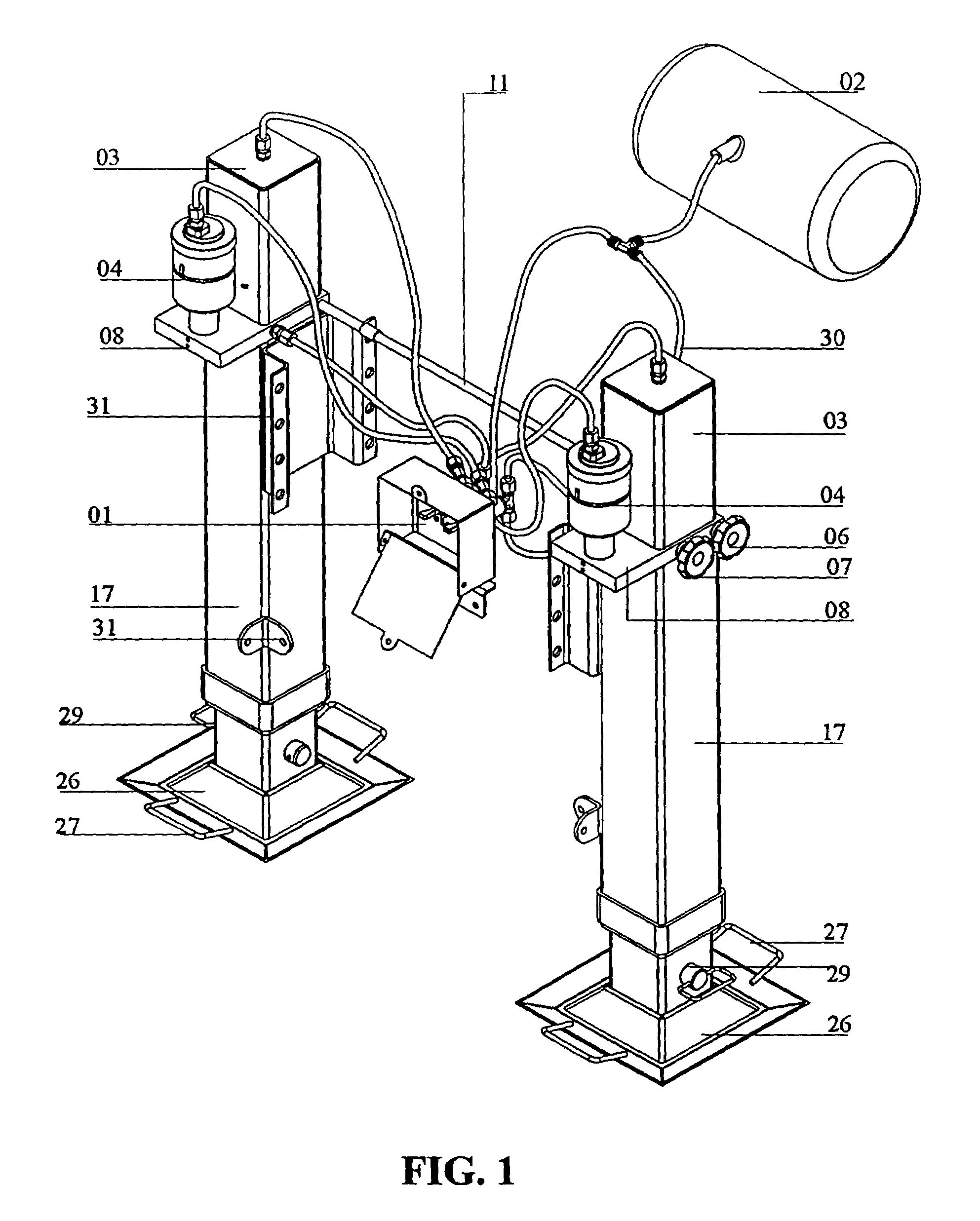
[0026]As it can be verified through the presentation of the figures, the aim of this patent is composed by the control key (01) that releases compressed air from the reservoir in the towing vehicle (02) and puts pressure over the hydraulic reservoir (03) and over the continuous pneumatic pump (04).

[0027]Underneath the continuous pneumatic pump (04) the cartridge valve (05), gloves (06) and (07), and valve control (08) can be all seen, having connection to descend the oil (10) to the entry (09), supply of air (11) and (12) and the return of the air to the system (R). The cartridge valve (05) is composed by the spheres (13) and (14), and the orifices (15) and (16), and the entry and exit for oil, respectively.

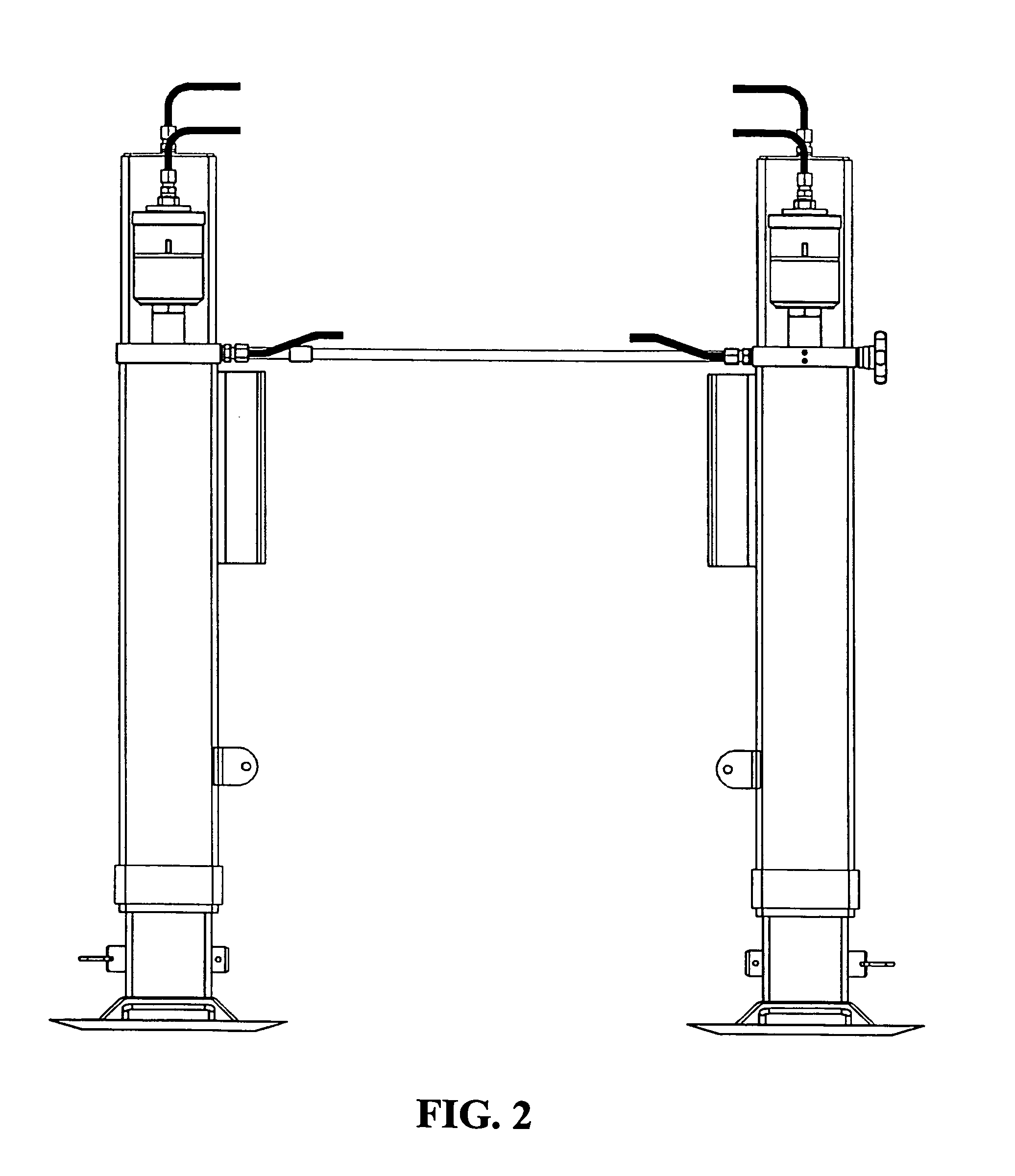
[0028]The telescopic boom (17) is made internally by the inner casing (18), a piston (19), hydraulic gaskets (20), pneumatic gaskets (21), a plunger (22) and an air entry (23) for the return of the piston. Externally, the telescopic boom (17) contains an upper (24) and a lower so...


PUM


Abstract

“DISPOSITION INTRODUCED TO HYDROPNEUMATIC JACK”, according to description of the report and the annexed illustrations, it is about a new disposition for a hydropneumatic device that is used to lift and support hauler and semi-haulers, whereby the device was designed to offer more operational easiness to the driver through the increase of speed, as well as the durability of the set.

Description

BACKGROUND OF THE INVENTION[0001]This patent for the Utility Model refers to a new disposition that was introduced to a hydropneumatic device which is used to lift and support haulers and semi-haulers, whereby such device has been projected to offer more easiness to the driver during operations through the increase of speed, as well as durability in the set.[0002]The state of the technique, which is the reason for this perfected construction, is known by means of patents MU 8201270-9 and MU 8203002-2, from the same petitioner.[0003]Patent MU 8201270-9 refers to a hydraulic lifting device for haulers and semi-haulers that is composed of a squared structure in steel, fixed by means of screws at the front of a semi-hauler, which supports the implement and also helps in its elevation, facilitating the coupling or uncoupling of a towing vehicle; it consists of a independent reservoir for hydraulic oil on each device, on both the left and right sides of the hauler or semi-hauler, operated...

Claims


Application Information

Patent Timeline
Patent Type & Authority Patents(United States)
IPC IPC(8): B66F3/24B60S9/12B66F7/26
CPCB66F3/24B60S9/12
Inventor SANTOS, VITOR HUGO DUARTE
Owner KEKO ACESSORIOS
Why Eureka
Try Eureka