Electronic firearm sight, and method of operating same

a technology of electronic and automatic adjustment, applied in the field of electronic firearm sight, can solve the problems of difficult assessment of how, unsatisfactory in all respects, and change in mechanical adjustment, and achieve the effect of facilitating digital adjustment of the position of the reticl

Active Publication Date: 2007-11-06
RAYTHEON CO
View PDF78 Cites 67 Cited by
  • Summary
  • Abstract
  • Description
  • Claims
  • Application Information

AI Technical Summary

Benefits of technology

[0009]A different form of the invention involves an apparatus which includes a viewing section that permits a user to view an image of a scene in association with a digital reticle, the viewing section including a reticle adjustment portion which facilitates digital adjustment of the position of the reticle relative to the image.
[0013]Still another form of the invention involves an apparatus having a firearm sight which includes: a viewing section configured to permit a user to view an image of a scene in association with a digital reticle; a reticle adjustment portion which facilitates digital adjustment of the position of the reticle relative to the image, the reticle adjustment portion being responsive to radiation received by the firearm sight which is representative of a position of a firearm bore for automatically adjusting the position of the reticle to effect an alignment of the reticle in relation to the firearm bore.

Problems solved by technology

Although existing firearm sights of this type have been generally adequate for their intended purposes, they have not been satisfactory in all respects.
Over time, these mechanical adjustments are subject to change, for example due to factors such as vibration, shock and wear.
When the target is relatively small, it can be difficult for the user to assess how precisely he or she is holding the reticle on the target.
For example, one user may not be able to hold the firearm quite as steady as another user, resulting in differences in accuracy.
However, in each case, the aiming errors can be so small that it is difficult for either user to perceive these errors by simply observing the relative positions of the reticle and target.
In contrast, the human factor is not repeatable or predictable, and thus it is difficult to assess this factor or compensate for it.
Due to a variety of factors such as variation in bullet caliber, this attempt to predict the time at which the trigger was pulled is inherently imprecise, and often results in the saving of an image which is not particularly useful because it represents a point in time too far before or too far after the actual trigger pull.
Moreover, the need to buffer a large number of images makes it necessary to dedicate a relatively large amount of memory to this function, which is undesirable.
This process is very time consuming, and is also relatively expensive, due to the cost of targets, bullets, transportation to the target range, fees for use of the target range, and so forth.

Method used


Image

  • Electronic firearm sight, and method of operating same
  • Electronic firearm sight, and method of operating same
  • Electronic firearm sight, and method of operating same

Examples


Embodiment Construction

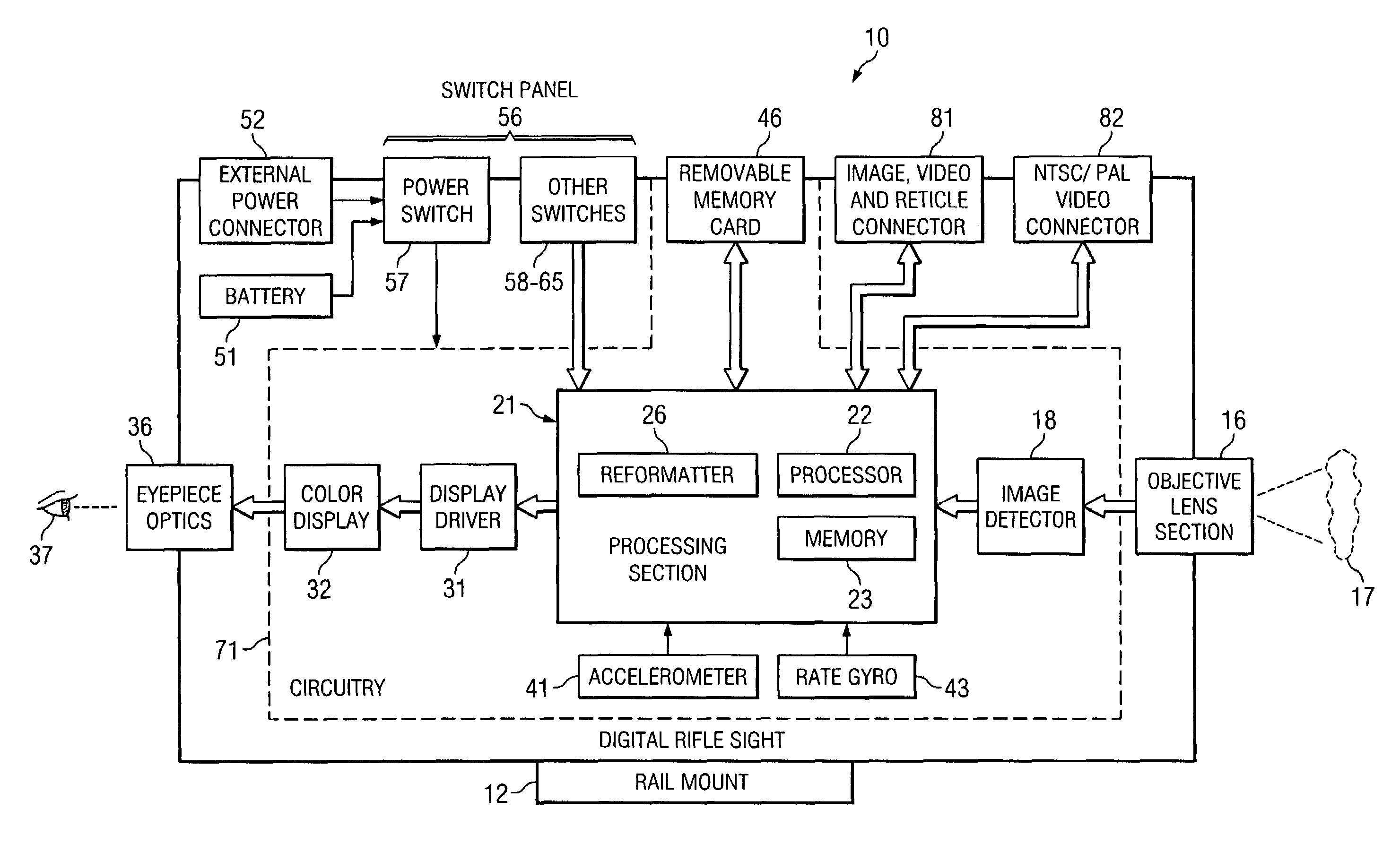
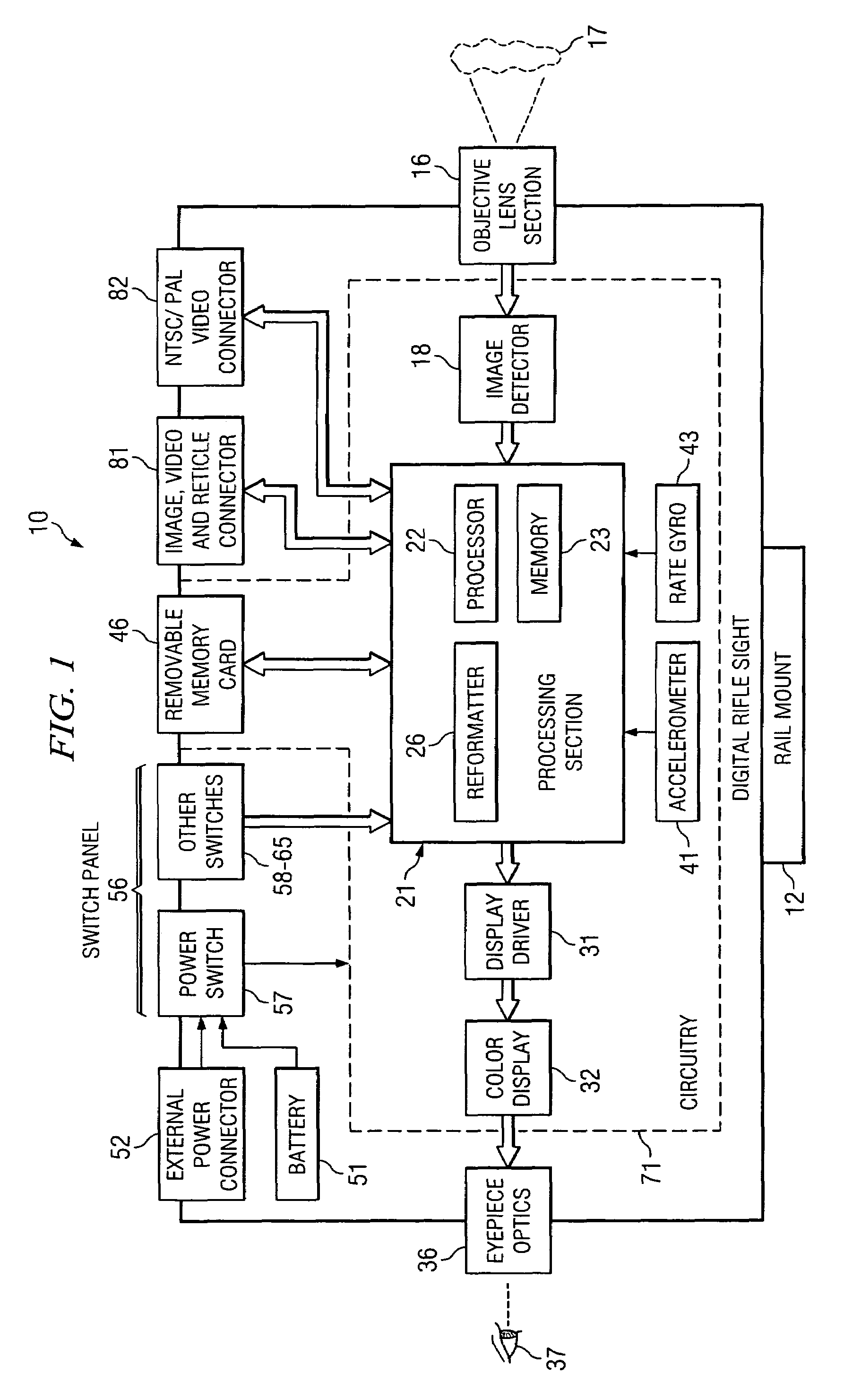
[0020]FIG. 1 is a block diagram showing an apparatus which is a digital rifle sight 10, and which embodies aspects of the present invention. Although the sight 10 is sometimes referred to herein as a “rifle” sight, it can actually be used not only with rifles, but also with other types of firearms, such as target pistols. The sight 10 includes a rail mount 12, which can fixedly and securely mount the sight 10 on the barrel of a firearm.

[0021]The sight 10 includes an objective lens section 16 of a known type. In the disclosed embodiment, the lens section 16 has a field of view (FOV) of 5°, but it could alternatively have some other field of view. The lens section 16 optically images a remote scene or target 17 onto an image detector 18. In the disclosed embodiment, the image detector 18 is a charge coupled device array (CCD array) of a known type, which has 1,920,000 detector elements that each correspond to a respective pixel in each image produced by the image detector 18, and whic...


PUM


Abstract

A firearm sight can detect engagement of a firing pin with a cartridge, and can respond to this event by saving an image which shows a target and reticle at a point in time just prior to the detected event. An electronic reticle can be downloaded into the sight. The effective position of the reticle within the sight can be adjusted electronically, and a zoom factor of the sight can be adjusted electronically. The sight can sense approximately transverse movement thereof, and can provide a user with an indication of the amount of transverse movement. With the use of an additional device, the sight can automatically align its reticle to the bore of a firearm on which the sight is mounted.

Description

TECHNICAL FIELD OF THE INVENTION[0001]This invention relates in general to a device which facilitates accurate aiming of a firearm and, more particularly, to a firearm sight mounted on the firearm, through which a user observes a potential target.BACKGROUND OF THE INVENTION[0002]Over the years, various techniques and devices have been developed to help a person accurately aim a firearm, such as a rifle or target pistol. One common approach is to mount on the firearm's barrel a sight or scope, through which the person views the intended target in association with a reticle, often with a degree of magnification. Although existing firearm sights of this type have been generally adequate for their intended purposes, they have not been satisfactory in all respects.[0003]For example, existing sights typically are passive optical devices with mechanical adjustments. For example, they have fixed reticles with mechanical reticle adjustments, and / or mechanical adjustments to vary the magnific...

Claims


Application Information

Patent Timeline
Patent Type & Authority Patents(United States)
IPC IPC(8): H04N7/18F41G1/54F41G3/16F41G3/26
CPCF41G1/54F41G3/16F41G1/00
Inventor TOWERY, CLAY E.FLORENCE, JAMES M.
Owner RAYTHEON CO
Why Eureka
Try Eureka