Ring binder mechanism

a technology of ring binding and ring member, which is applied in the field of ring binding, can solve the problems of difficult opening and closing of ring members, hazardous snapping action, gaps on closed rings, etc., and achieves the effect of preventing operator injury and being easy to open or clos

Inactive Publication Date: 2007-11-20
WORLD WIDE STATIONARY MFG CO LTD
View PDF136 Cites 75 Cited by
  • Summary
  • Abstract
  • Description
  • Claims
  • Application Information

AI Technical Summary

Benefits of technology

[0005]Among the several objects and features of the present invention may be noted the provision of a ring binder mechanism which inhibits injury to operators; the provision of such a mechanism which is easily opened or closed; the provision of such a mechanism which provides uniform clamping force in each ring; the provision of such a mechanism which may be securely locked; and the provision of such a mechanism which provides a locking force to secure the mechanism in the closed position.

Problems solved by technology

One drawback to ring binders of the prior art is that when ring members are being closed, they snap shut with a strong magnitude of force which can cause injury.
Unfortunately, that magnitude of force is also applied to the ring members while they are being opened or closed, causing difficulty in opening and closing the ring members, as well as the hazardous snapping action.
Further, the clamping force within each ring is not uniform with the clamping force in other rings, causing uneven movement and potentially resulting in gaps on closed rings.

Method used


Image

  • Ring binder mechanism
  • Ring binder mechanism
  • Ring binder mechanism

Examples


Embodiment Construction

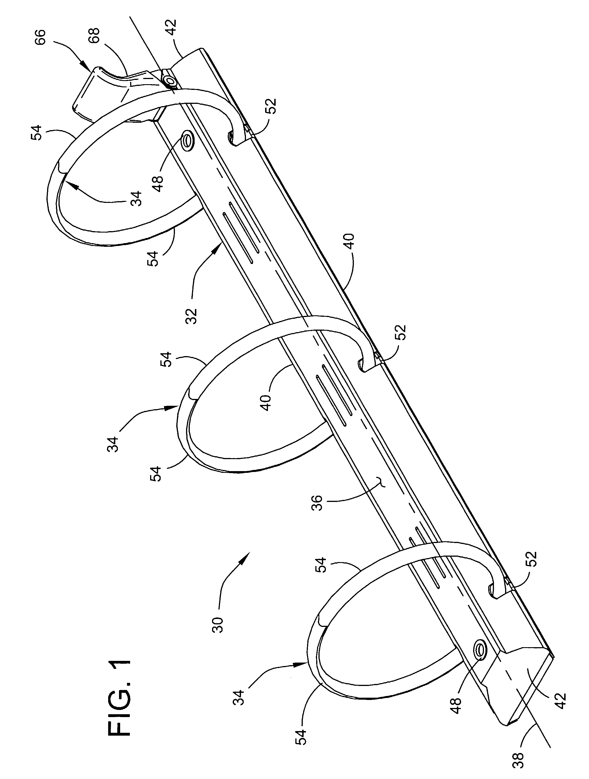
[0034]Referring now to the drawings and in particular to FIG. 1, a ring binder mechanism according to the present invention for retaining loose leaf pages is indicated generally at 30. The mechanism 30 includes an elongate plate 32 and three rings, each indicated generally at 34, for holding loose leaf pages.

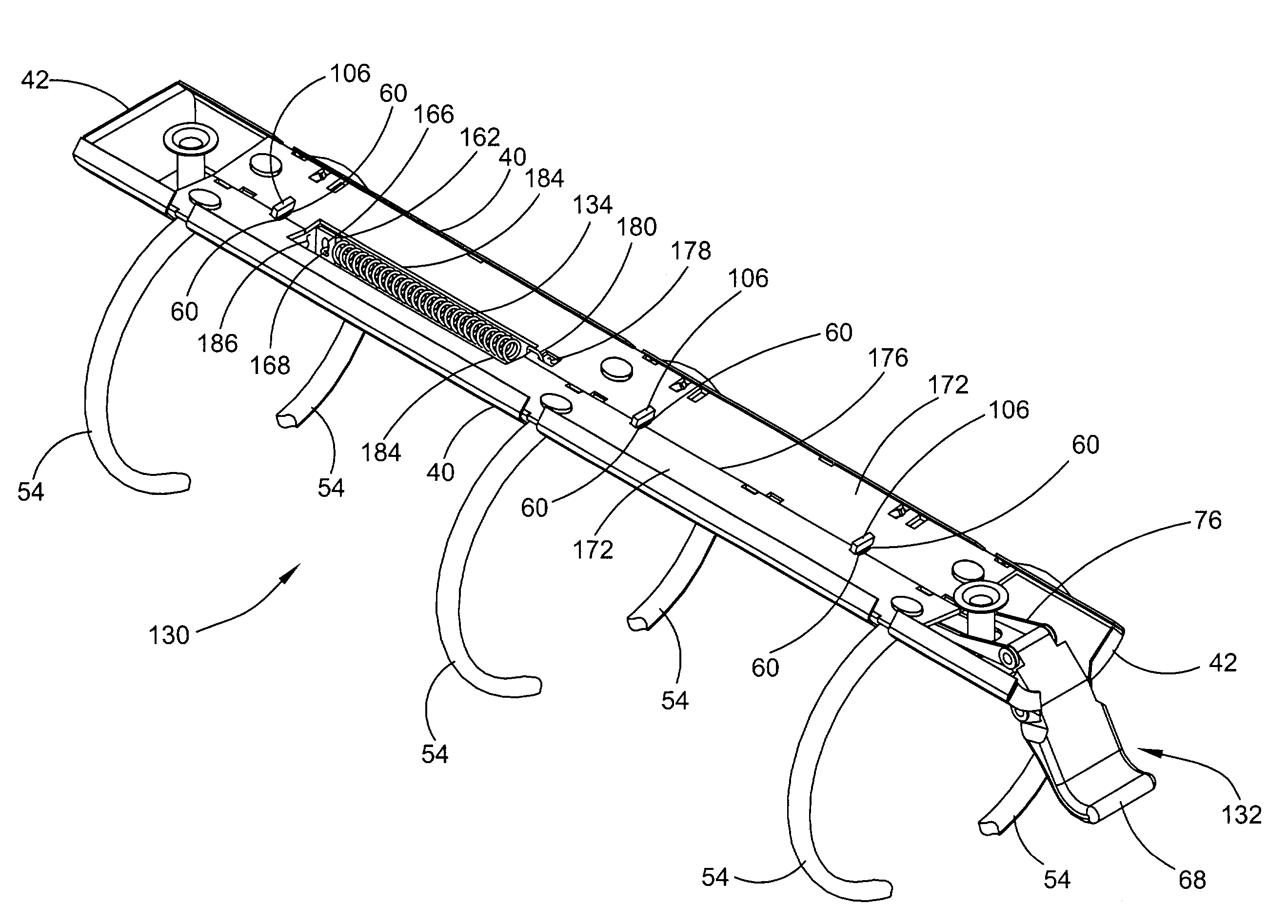
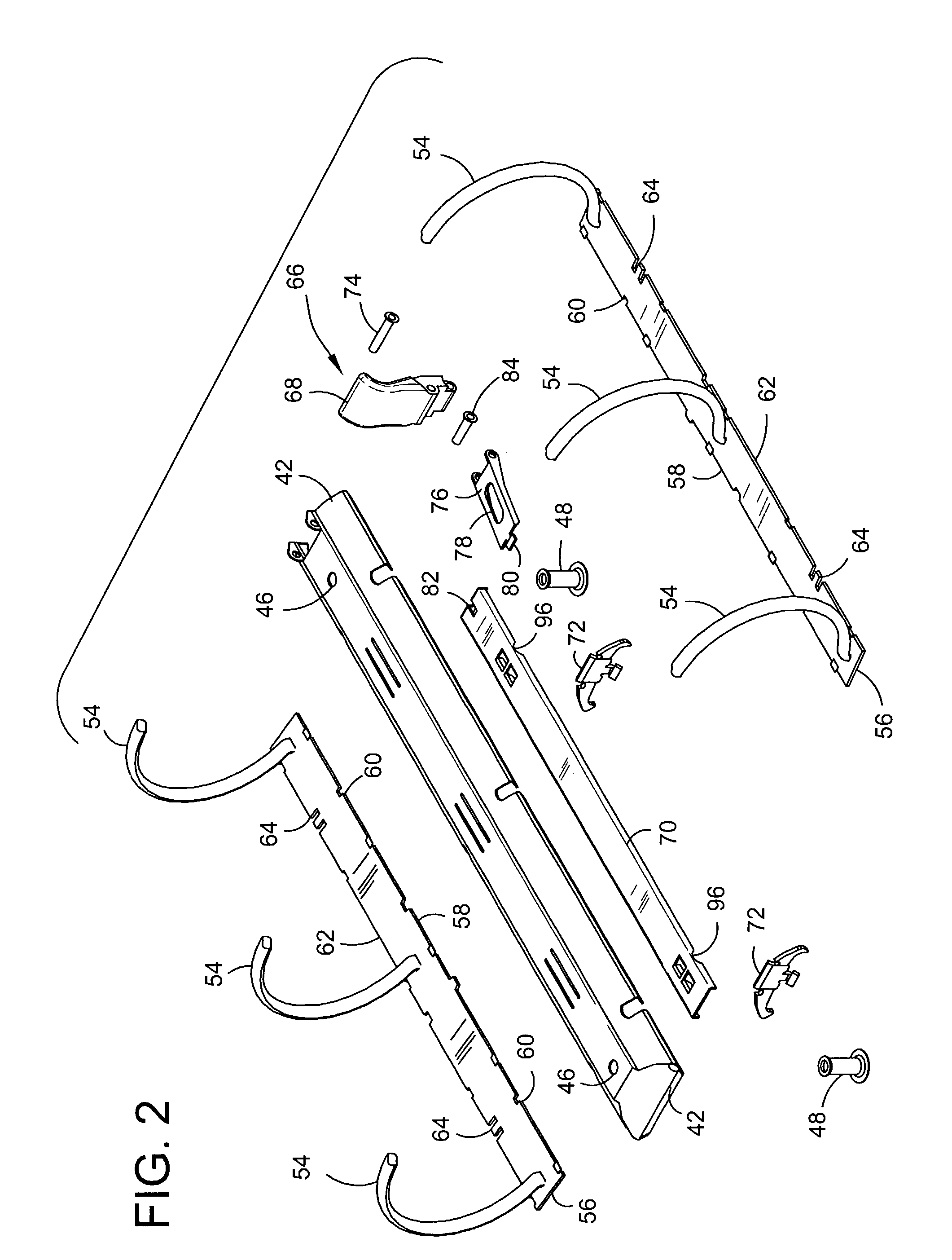
[0035]The plate 32 is shaped as an elongated rectangle with a uniform, generally arch-shaped elevated profile having at its center a raised plateau 36. The plate 32 has a longitudinal axis 38, two generally opposite longitudinal edges 40, and two generally opposite transverse ends 42. A bent under rim 44 (FIG. 9) is formed along the longitudinal edges 40. The elongate plate 32 is made of metal or other suitable material which is sufficiently rigid to provide a stable mount for other components of the mechanism, while being lightweight to conserve material and manufacturing costs. Two openings 46 (FIG. 2) are provided for receiving and attaching mounting posts 48 to secure the me...


PUM


Abstract

A ring binder mechanism for retaining loose leaf pages. The mechanism includes a rigid, elongate plate having a longitudinal axis. Hinge plates are supported by the plate for pivoting relative to the elongate plate. Rings for holding loose leaf pages include ring members mounted on the hinge plates and moveable between a closed position and an open position. A control structure is supported by the elongate plate and controllably pivots the hinge plates to move the ring members between the closed and open positions. The control structure has a travel bar connected to the hinge plates for moving the hinge plates between the closed and open positions. A spring biases the travel bar to a position toward the closed position of the hinge plates.

Description

CROSS-REFERENCE TO RELATED APPLICATION [0001]This application is a Continuation-in-Part of U.S. patent application Ser. No. 09 / 683,205, filed Nov. 30, 2001 now U.S. Pat. No. 6,749,357, the entire text of which is hereby incorporated herein by reference in its entirety.BACKGROUND OF THE INVENTION [0002]This invention relates to binders for holding loose leaf pages, and in particular to an improved mechanism for opening and closing binders.[0003]A ring binder retains loose leaf pages, such as hole-punched papers, in a file or notebook. It features ring members for retaining the papers which may be selectively opened to add or remove papers, or closed to retain papers while allowing them to be moved along the ring members. Levers are typically provided on both ends of the binder for moving the ring members between the open and closed positions.[0004]One drawback to ring binders of the prior art is that when ring members are being closed, they snap shut with a strong magnitude of force ...

Claims


Application Information

Patent Timeline
Patent Type & Authority Patents(United States)
IPC IPC(8): B42F13/20B42F3/04B42F13/26
CPCB42F13/26
Inventor CHENG, HUNG YUCHENG, HO PING
Owner WORLD WIDE STATIONARY MFG CO LTD
Why Eureka
Try Eureka