
Method of detecting RF powder delivered to a load and complex impedance of the load

a load and load technology, applied in the direction of resistance/reactance/impedence, impedence measurement, instruments, etc., can solve the problems of severe impedance mismatch between the plasma chamber, the output of the rf power generator may become unstable, and the signal generated by the rf power generator can be severely degraded

Active Publication Date: 2007-11-20
ASM AMERICA INC
View PDF29 Cites 78 Cited by
  • Summary
  • Abstract
  • Description
  • Claims
  • Application Information

AI Technical Summary

Benefits of technology

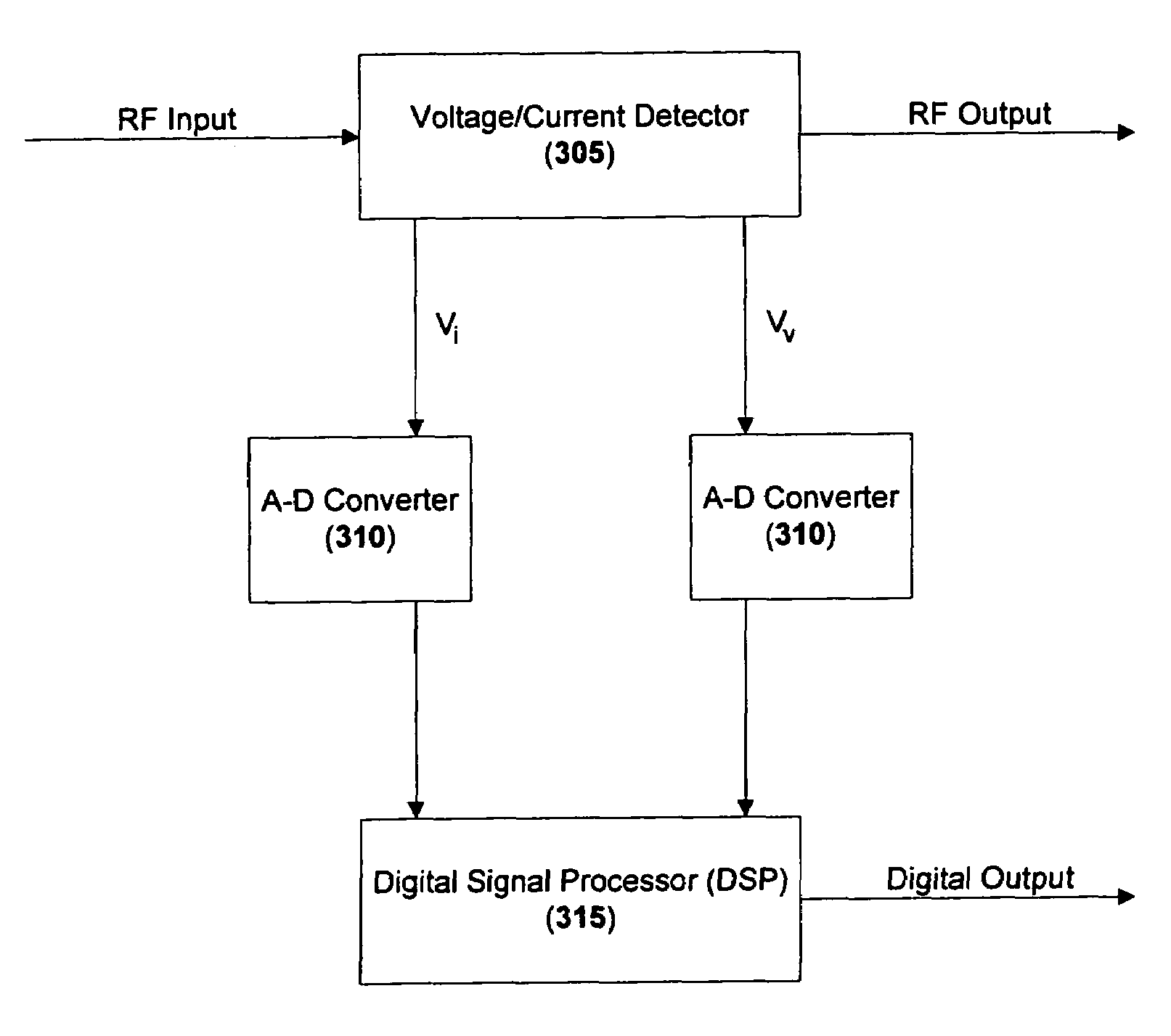
"The patent describes a method and system for detecting characteristics of a load using a RF power generator. The system includes a detecting device, an A-D converter, and a DSP. The detecting device samples the characteristics of the signal at a sampling frequency to produce a digital sampled signal. The DSP then determines one or more characteristics of the load from the digital form of the characteristics of the signal. The technical effect of this patent is to provide a more accurate and efficient method for detecting the characteristics of a load."

Problems solved by technology

Typically, a severe impedance mismatch between the RF power generator and the plasma chamber is present.
Because of non-linearities in the plasma chamber and losses in the line and / or in the impedance matching network, the complete RF signal does not reach the plasma chamber.
One problem with the above-described methods and systems is that the signal generated by the RF power generator can severely degrade due to an impedance mismatch between the RF power generator (or other components) and the plasma chamber.
Another problem occurs when an impedance matching network is used between the output of the RF power generator and the input of the plasma chamber.
As such, the output of the RF power generator may become unstable due to interaction between the control loop of the RF power generator and the control loop of the impedance matching network.
In addition, the use of an aliasing frequency that is independent of the RF fundamental frequency can result in a non-uniform sampled signal.
However, such a system requires filtering at a particular harmonic frequency.
While this may provide information at the particular harmonic frequency, information at the fundamental frequency or other harmonic frequencies may not be obtainable using such a system.

Method used


Image

  • Method of detecting RF powder delivered to a load and complex impedance of the load
  • Method of detecting RF powder delivered to a load and complex impedance of the load
  • Method of detecting RF powder delivered to a load and complex impedance of the load

Examples


Embodiment Construction

[0023]An RF generator may be used to deliver RF power to a load. In an embodiment, the RF generator may directly deliver the RF power to the load via a coaxial cable. In an alternate embodiment, the RF generator may directly deliver the RF power to the load via a transformation network. Other means of directly or indirectly delivering power to a load may also be used within the scope of the present disclosure.

[0024]In an embodiment, the load may include one or more of a plasma chamber, a gaseous tube, a resistive load, and / or a complex load including resistive and / or reactive components, such as a capacitor and / or an inductor. Additional or alternate load devices may also be used within the scope of the present disclosure.

[0025]A voltage and / or current detecting device, such as 305 in FIG. 3, may be placed at a point where the RF power or impedance is to be measured. For example, the voltage and / or current detecting device 305 may be placed at the output of the RF generator, within ...


PUM


Abstract

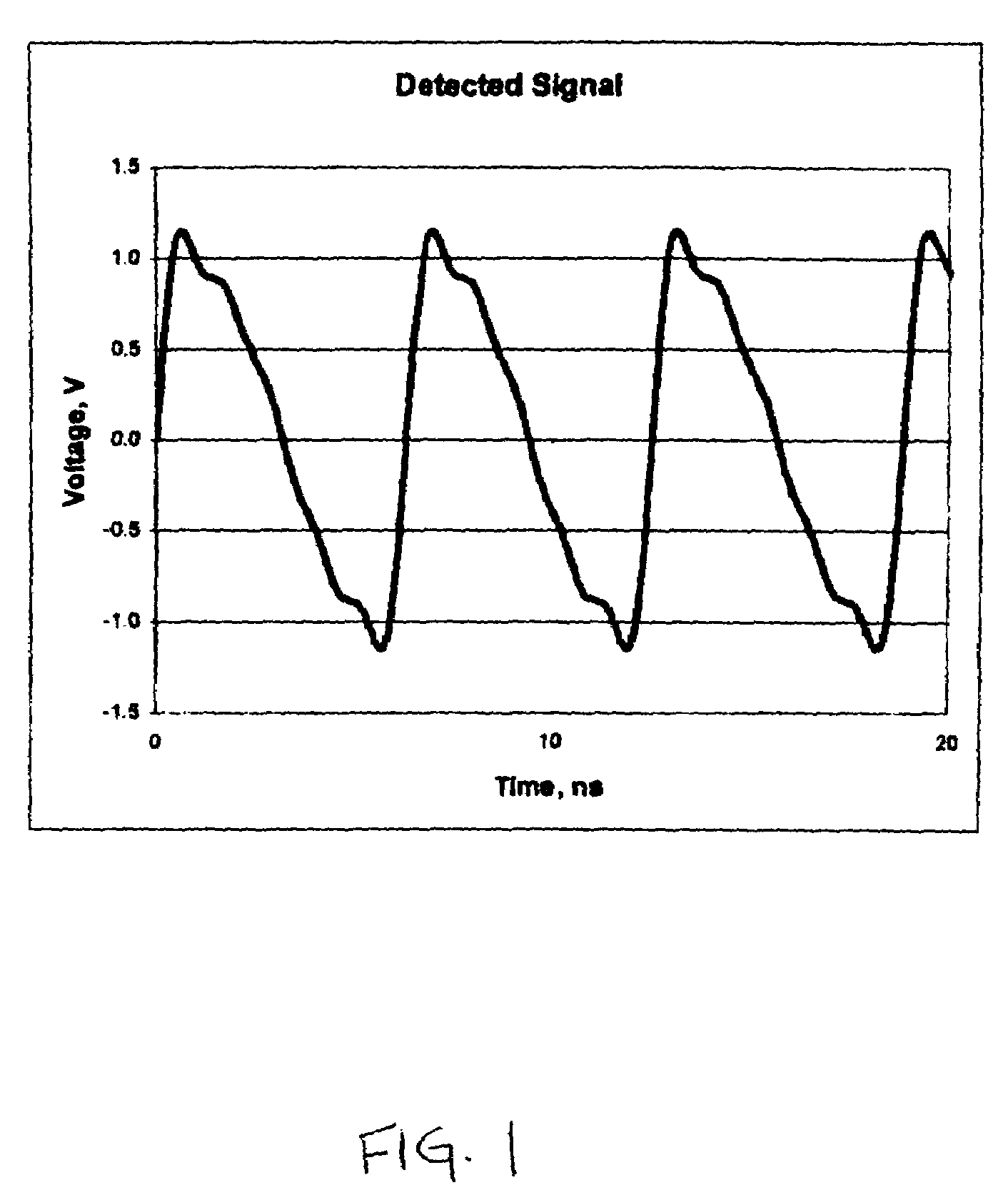
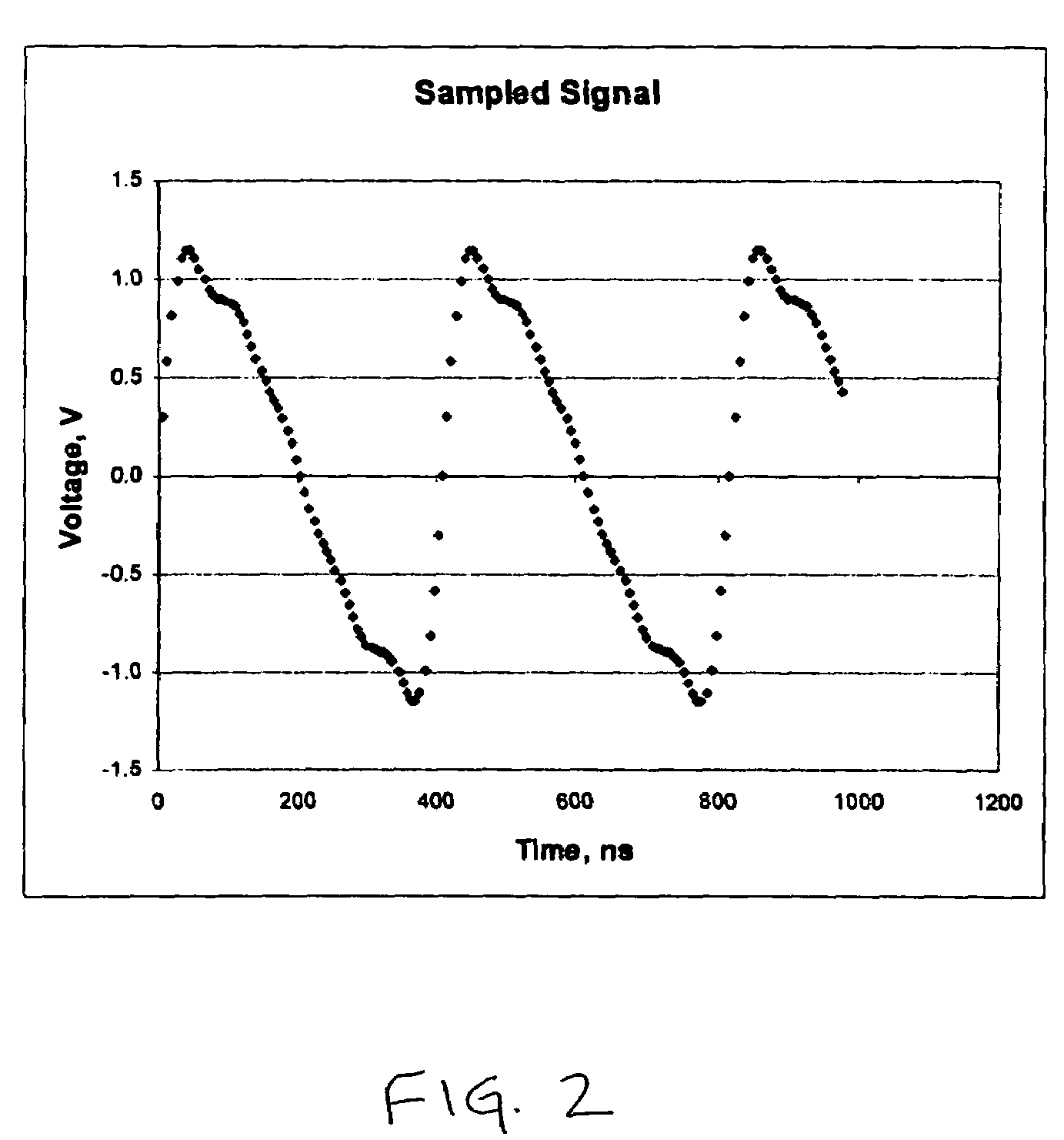
Methods and systems of detecting one or more characteristics of a load are disclosed. One or more characteristics of a first signal may be detected at the output of a Radio Frequency (RF) power generator. The first signal may have a fundamental frequency. The one or more characteristics of the first signal may be sampled at a sampling frequency to produce a digital sampled signal. The sampling frequency may be determined based on a function of the fundamental frequency of the first signal. One or more characteristics of a load in communication with the RF power generator may then be determined from the digital sampled signal.

Description

CROSS-REFERENCE TO RELATED APPLICATIONS[0001]This patent application claims priority to, and incorporates by reference in its entirety, U.S. Provisional Patent Application No. 60 / 643,014 entitled “Method of Detecting RF Power Delivered to a Load and Complex Impedance of the Load, Using Fast Fourier Transform (FFT)” and filed Jan. 11, 2005.BACKGROUND[0002]1. Technical Field[0003]The disclosed embodiments generally relate to the field of power and impedance measurement.[0004]2. Description of the Related Art[0005]In a typical RF plasma generator arrangement, a high-power RF source (RF power generator) produces an RF signal at a known frequency that is supplied along a power conduit to a plasma chamber. Typically, a severe impedance mismatch between the RF power generator and the plasma chamber is present. Accordingly, an impedance matching network is conventionally interposed between the RF power generator and the plasma chamber.[0006]Because of non-linearities in the plasma chamber a...

Claims


Application Information

Patent Timeline
Patent Type & Authority Patents(United States)
IPC IPC(8): G01R23/16G06F19/00
CPCH05H1/46H01J37/32174G01R27/16H05H1/24G01R23/15G01R23/20
Inventor BHUTTA, IMRAN AHMED
Owner ASM AMERICA INC
Learn More