Gas turbine combustion apparatus

a combustion apparatus and gas turbine technology, applied in mechanical equipment, lighting and heating equipment, machines/engines, etc., can solve the problems of large nosub>x/sub>, adverse influence of the flow of compressed air, and the inability of existing facilities to comply with nosub>x/sub>emission regulations

Active Publication Date: 2007-11-27
MITSUBISHI HEAVY IND LTD
View PDF15 Cites 23 Cited by
  • Summary
  • Abstract
  • Description
  • Claims
  • Application Information

AI Technical Summary

Benefits of technology

[0012]The present invention has been accomplished to solve the above-mentioned problems. It is an object of the present invention to provide a gas turbine combustion apparatus which can be installed in existing facilities and which can stably decrease NOx in an exhaust gas according to each load.
[0019]In the gas turbine combustion apparatus according to the present invention, for solving the above problems, the exhaust control means may be an opening and closing valve provided in an exhaust pipe which the exhaust port has. According to this feature, the amount of exhaust of compressed air discharged into the turbine casing chamber can be reliably controlled. Since compressed air introduced into the combustor can be held at a constant level by this control, NOx in the exhaust gas can be decreased.
[0020]In the gas turbine combustion apparatus according to the present invention, for solving the above problems, the recovery means may be a circular pipe extending along the circumferential direction within the turbine casing chamber, and formed in a toroidal shape. According to this feature, compressed air bled by the respective bleeding means can be recovered reliably.
[0026]In the gas turbine combustion apparatus according to the present invention, for solving the above problems, the exhaust port may be a manhole used during work within the turbine casing chamber. According to this feature, the exhaust port can be installed at a low cost even in the existing gas turbine combustion apparatus in which it is difficult to decrease NOx in the exhaust gas. Moreover, NOx in the exhaust gas can be stably decreased in response to each load.

Problems solved by technology

However, among gas turbines currently in operation, there are those whose existing facilities cannot comply with the NOx emission regulations. FIG. 6 shows a conventional gas turbine combustion apparatus which poses difficulty in decreasing NOx in an exhaust gas.
As a result, oversupply of compressed air occurs during combustion inside the combustor 101, producing large amounts of NOx.
A greatly curved outer site of the bypass pipe 112, and a sharply bent inner site thereof are problematical in terms of strength, and stress imposed on these sites during operation of the gas turbine combustion apparatus may result in damage.
Furthermore, the formation of such a pipe shape leads to adverse influence on the flow of compressed air passing inside the bypass pipe 112.

Method used


Image

  • Gas turbine combustion apparatus
  • Gas turbine combustion apparatus
  • Gas turbine combustion apparatus

Examples


Embodiment Construction

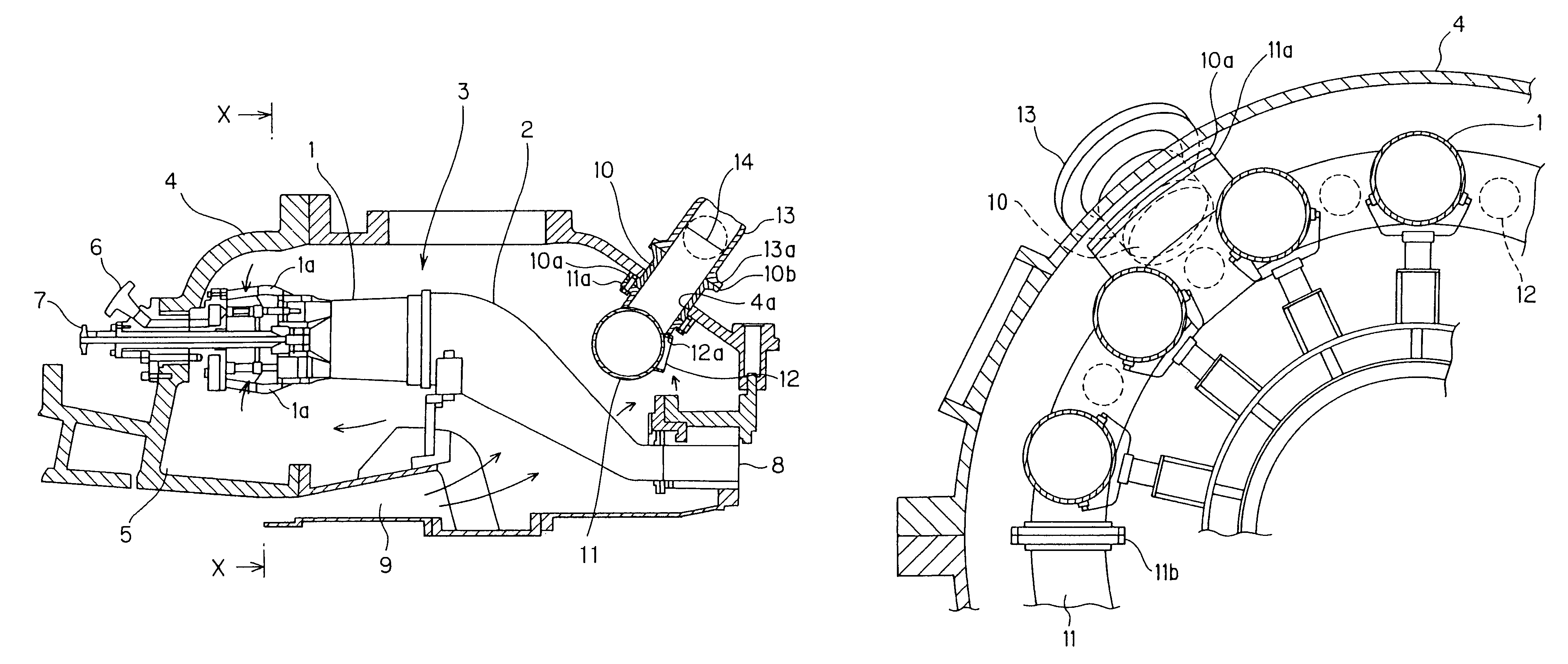
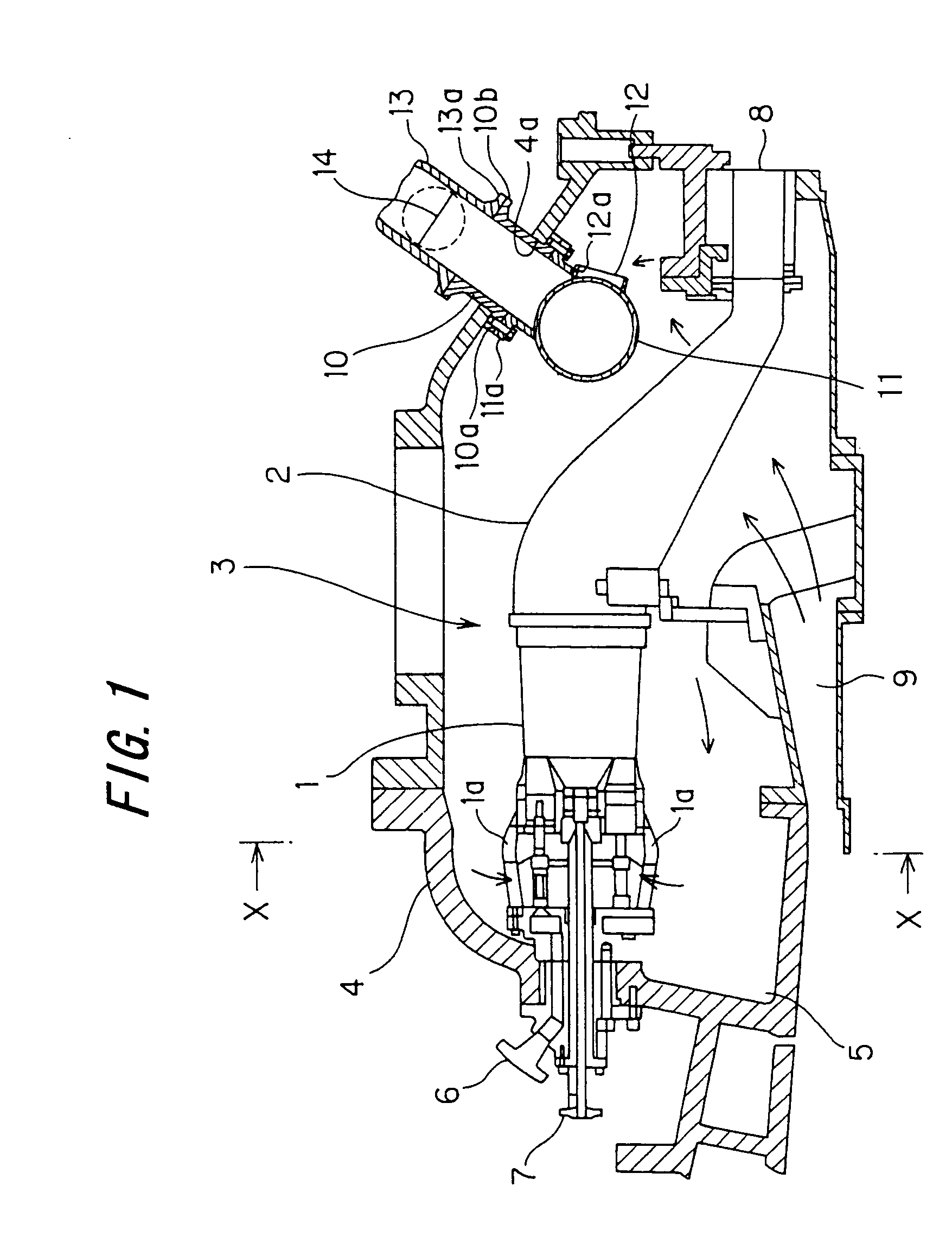
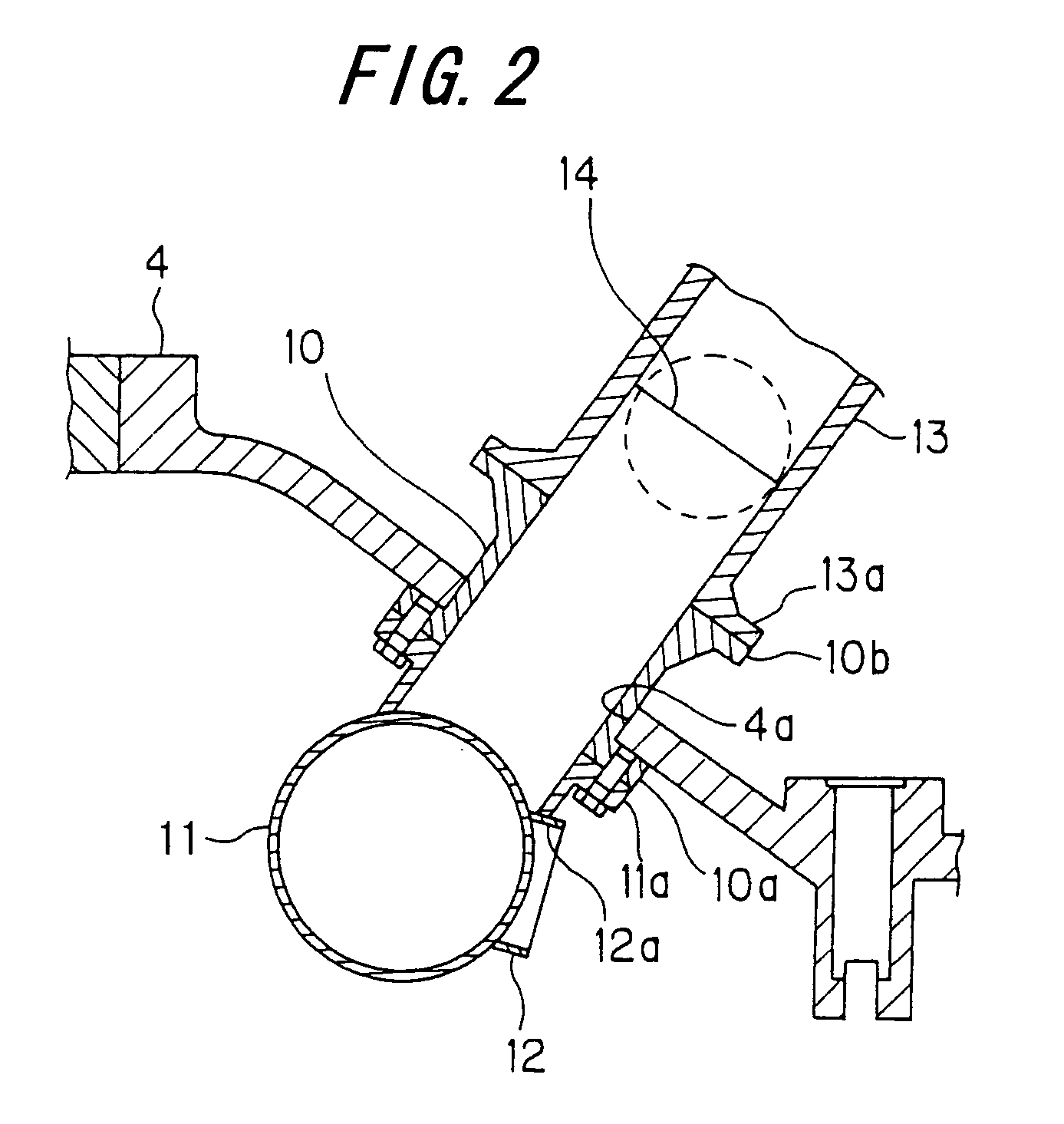
[0035]FIG. 1 is a sectional view of a gas turbine combustion apparatus according to an embodiment of the present invention. FIG. 2 is an enlarged view of essential parts of the gas turbine combustion apparatus shown in FIG. 1. FIG. 3 is a sectional view taken on line X-X of FIG. 1. FIG. 4 is a sectional view of a gas turbine combustion apparatus showing another embodiment of the present invention. Arrows in FIG. 1 represent the flow of compressed air.

[0036]As shown in FIGS. 1, 2 and 3, a combustor 3 comprising a combustor inner tube 1 and a combustor transition pipe 2 connected together is installed in a turbine casing chamber 5 which is a space defined by a casing 4. Fourteen of the combustors 3 are installed in a circumferential direction of the turbine casing chamber 5 and with equal spacing.

[0037]A fuel supply pipe 6 for supply of fuel is provided in a front end portion of the combustor inner tube 1. Fuel, which has passed through the fuel supply pipe 6, is supplied to a fuel in...


PUM


Abstract

A gas turbine combustion apparatus has a plurality of combustors provided in a circumferential direction within a turbine casing chamber formed by a casing, each combustor comprising a combustor inner tube and a combustor transition pipe, but lacks a turbine bypass mechanism for controlling the amount of compressed air discharged from a compressor into the turbine casing chamber. The combustion apparatus comprises an exhaust port member fitted into a manhole opening in the casing and communicating with the outside of the turbine casing chamber, bleeding pipes for uniformly bleeding compressed air discharged into the turbine casing chamber, a circular pipe for recovering compressed air bled by the bleeding pipes and discharging the compressed air to the exhaust port member, and an opening and closing valve for controlling the amount of exhaust which the circular pipe discharges to the outside of the turbine casing chamber via the exhaust port member, thereby possessing a turbine bypass mechanism.

Description

CROSS REFERENCE TO RELATED APPLICATION[0001]The entire disclosure of Japanese Patent Application No. 2003-409792 filed on Dec. 9, 2003, including specification, claims, drawings and summary, is incorporated herein by reference in its entirety.BACKGROUND OF THE INVENTION[0002]1. Field of the Invention[0003]This invention relates to a gas turbine combustion apparatus.[0004]2. Description of the Related Art[0005]In recent years, various improvements have been made on a combustion apparatus in a gas turbine in order to decrease the concentrations of NOx (nitrogen oxides) in an exhaust gas, thereby achieving low NOx in the exhaust gas of the gas turbine. Methods in wide use for this purpose are those in which the total amount of compressed air is not introduced into a combustor, but instead, a bypass valve is provided, and part of compressed air is bypassed through the bypass valve.[0006]As shown in FIG. 5, for example, a combustor 101 is composed of a combustor inner tube 102 and a comb...

Claims


Application Information

Patent Timeline
Patent Type & Authority Patents(United States)
IPC IPC(8): F02C3/00F01D25/24F01D17/00F01D25/28F01D25/30F02C7/00F02C7/057F02C9/00F02C9/18F02C9/20F23R3/16F23R3/26F23R3/42
CPCF23R3/26F02C9/18
Inventor TERAZAKI, MASAOKANEZAWA, YOSHIYUKIHORIKAWA, HIDETO
Owner MITSUBISHI HEAVY IND LTD
Why Eureka
Try Eureka