
Container

a technology for containers and storage containers, applied in the field of containers, can solve the problems of difficult handling in practice, for example a metered screw removal during an installation process, and achieve the effects of reducing transportation space, storage space and presentation space, and ensuring safety

Active Publication Date: 2007-11-27
ALTENLOH BRINCK & CO GMBH
View PDF14 Cites 23 Cited by
  • Summary
  • Abstract
  • Description
  • Claims
  • Application Information

AI Technical Summary

Benefits of technology

[0006]By means of the closure tab according to the invention which is attached to the upper side of the outer part and has a tear-off strip, the goods are reliably stored during transportation and during presentation on sales shelves and are protected from unauthorized removal. After the tear-off strip is detached, a tab section remaining on the inner part can be pushed during later use, with the inner part inserted, under the upper side wall of the outer part and can thereby act in a stabilizing manner, which is of advantage in particular in the case of heavy metal goods.
[0007]The division of the container into inner part and outer part in conjunction with a cuboidal configuration makes it possible to arrange a multiplicity of containers next to one another and one above another in a space-saving manner, thus enabling the costs for transportation space, storage space and presentation space to be reduced. The inserted drawer element imparts additional stability to the outer part by means of the double side wall which is produced, which impacts positively on the transportation properties and on the maximum stacking height. The division into two parts also proves advantageous in practice when using the packaged goods, since the goods, while remaining in the drawer element, can be completely removed and are easily accessible at the location of use.
[0008]A reduction in the height of the rear wall and a graduation, undertaken at this height, of the two side walls of the drawer element facilitate the insertion of the drawer element.

Problems solved by technology

Although the folding boxes of the prior art can be closed again, the handling in practice, for example a metered removal of screws during an installation process, proves difficult because of the closure device using closure flaps.

Method used


Image

  • Container
  • Container
  • Container

Examples


Embodiment Construction

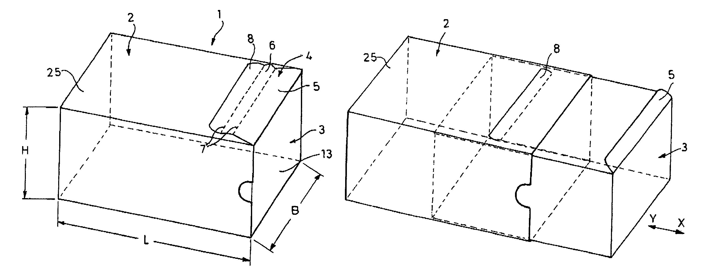
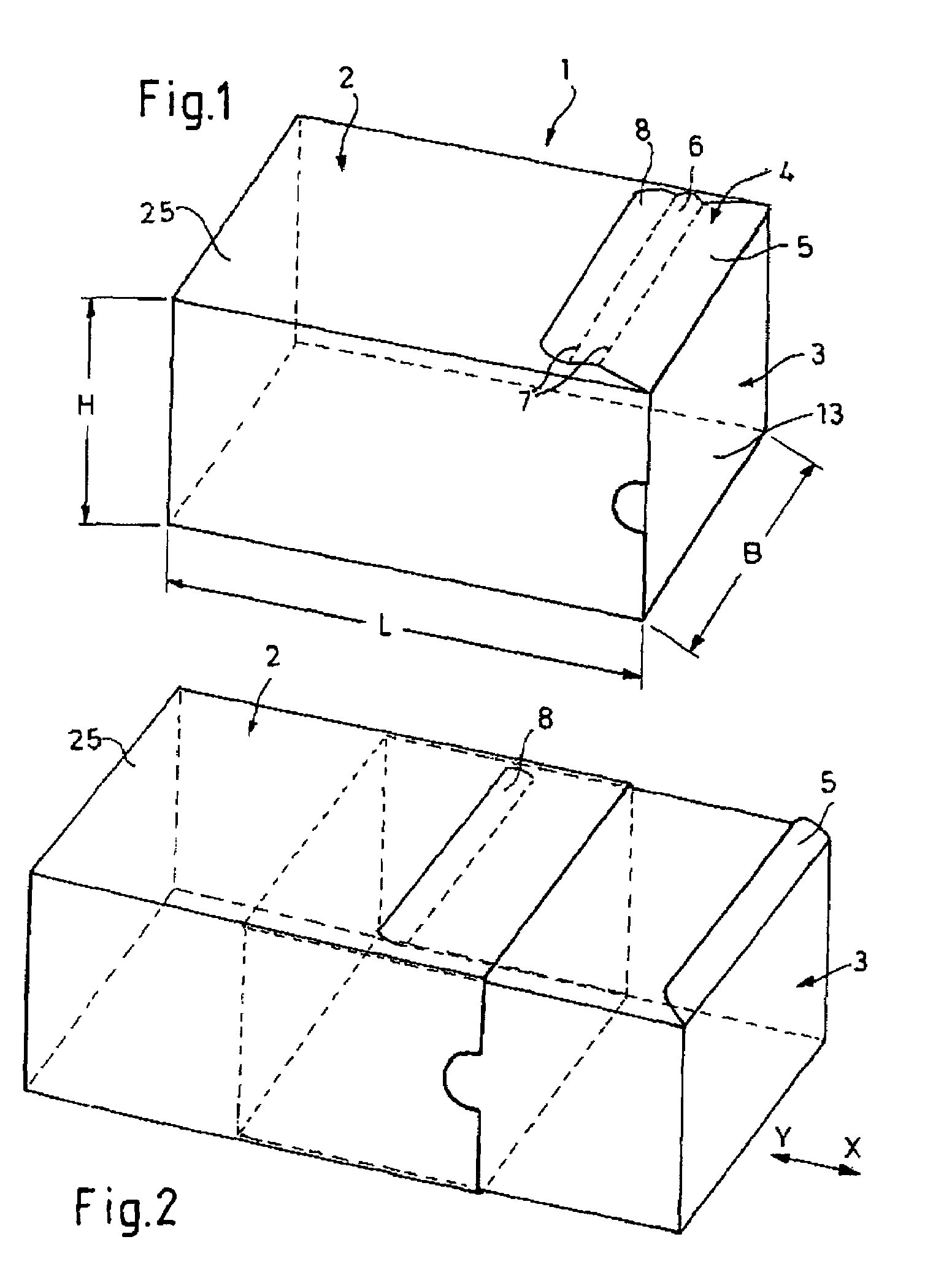
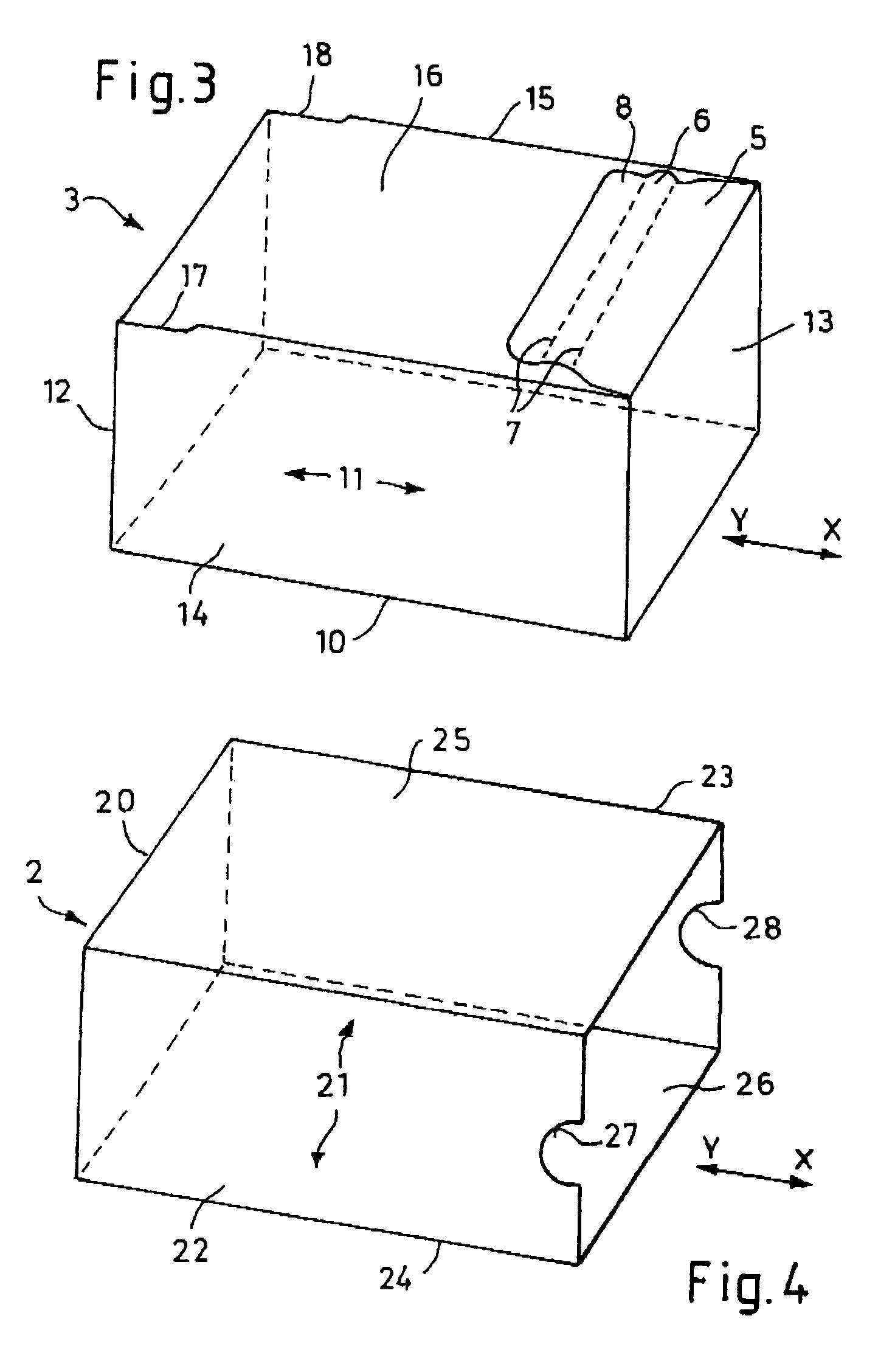
[0020]FIG. 1 shows a view of a container 1 according to the invention in the closed state, the container comprising an outer part 2 and an inner part 2. The inner part 3 is entirely inserted into the outer part 2 and is connected via a closure tab 4 to the outer part 3, the closure tab 4 having a closure-tab inner section 5 integrally formed on the inner part 3. Before the first opening of the container 1 via a preformed tear-off strip 6, the closure-tab inner section 5 is connected to a closure-tab outer section 8 by means of weakened material portions 7, in particular perforations. By simple pulling on the tear-off strip 6, the latter can be entirely detached over the entire region marked by the perforation and releases the closure-tab inner section 5 while the closure-tab outer section 8 remains on the outside of the outer part 2.

[0021]According to FIG. 2, the inner part 3, which is designed as a drawer element, can be pulled out of the outer part in the arrow direction X, with i...


PUM


Abstract

The present invention relates to a container, which comprises an inner part (3) for accommodating objects, in particular screws or the like, and an outer part (2) which surrounds the inner part (3) in the closed state of the accommodating container. In this case, the inner part (3) can be entirely accommodated by the outer part (2) and is connected via a closure tab (4), which is formed on the inner part (3), to the outer part (2) in such a manner that the closure tab (4) is fastened to the end of an outer side of the outer part (2), and the closure tab (4) can be severed by a tear-off strip (6), so that the inner part (3) can be released from the outer part.

Description

CROSS REFERENCE TO RELATED APPLICATIONS[0001]This application claims priority to German Utility Patent Application No. 20 2004 014 386.0 filed Sep. 16, 2004.FIELD OF THE INVENTION[0002]The present invention relates to a container, comprising an inner part for accommodating objects, in particular screws or the like, and an outer part which surrounds the inner part in the closed state of the container.BACKGROUND OF THE INVENTION[0003]As a packaging container for small parts, folding boxes of generally cuboidal design are well-known. A packaging device of this type is described in DE 195 41 904 A1. In order to make the packaging contents accessible by correct first opening of the packaging, a tear-off tab which detaches part of the packaging wall is often integrated in at least one side wall. For the later continuous removal of the contents, the container has to be able to be opened and freely accessible at least on one side. Although the folding boxes of the prior art can be closed ag...

Claims


Application Information

Patent Timeline
Patent Type & Authority Patents(United States)
IPC IPC(8): B65D5/38
CPCB65D5/38B65D5/54Y10S229/913
Inventor MITTMANN, RALFELSENHEIMER, WOLFGANG
Owner ALTENLOH BRINCK & CO GMBH
Learn More