Heater control for cotton candy spinner head

a heating element and spinner head technology, applied in the field of cotton candy machines, can solve the problems of cleaning, operation and maintenance, residual heat of the heating elements can burn sugar remaining in the spinner head, and adversely affect the operation and maintenan

Active Publication Date: 2007-11-27
GOLD MEDAL PRODS
View PDF6 Cites 5 Cited by
  • Summary
  • Abstract
  • Description
  • Claims
  • Application Information

AI Technical Summary

Benefits of technology

[0006]According to this aspect, the machine also includes a switch having a first state for energizing the heater element and the motor and a second state for de-energizing the heater element and the motor; and a delay circuit coupled with the switch and the motor. This delay circuit detects when the switch changes from its first state to its second state and, in response, prevents de-energizing the motor for a predetermined time period.
[0007]Another aspect of the present invention relates to a method for preparing cotton candy. According to this method, a motor is energized that rotates a spinner head for melting granulated sugar introduced thereinto, wherein the spinner head when rotating directs molten sugar filaments radially outward therefrom. Concurrently with, or optionally after, the energizing of the motor, a heater element that is located within the spinner head is energized as well. Next, input is received to de-energize said motor and said heater element and, in response to the received input, the heater element is de-energized but the motor is prevented from being de-energized for a predetermined period of time after de-energizing the heater element.

Problems solved by technology

A problem associated with cotton candy machines and one which adversely impacts the cleaning, operation and maintenance of the machines is that when the machine is turned off, the residual heat of the heating elements can burn sugar which remains in the spinner head.
Such residual burned sugar is difficult to clean and can move, while hot, to areas distant from the heater so that it does not melt upon start-up, thereby adversely impacting operation and maintenance.

Method used


Image

  • Heater control for cotton candy spinner head
  • Heater control for cotton candy spinner head
  • Heater control for cotton candy spinner head

Examples


Embodiment Construction

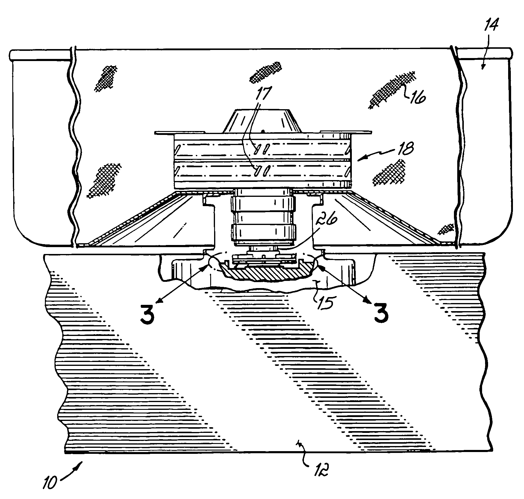
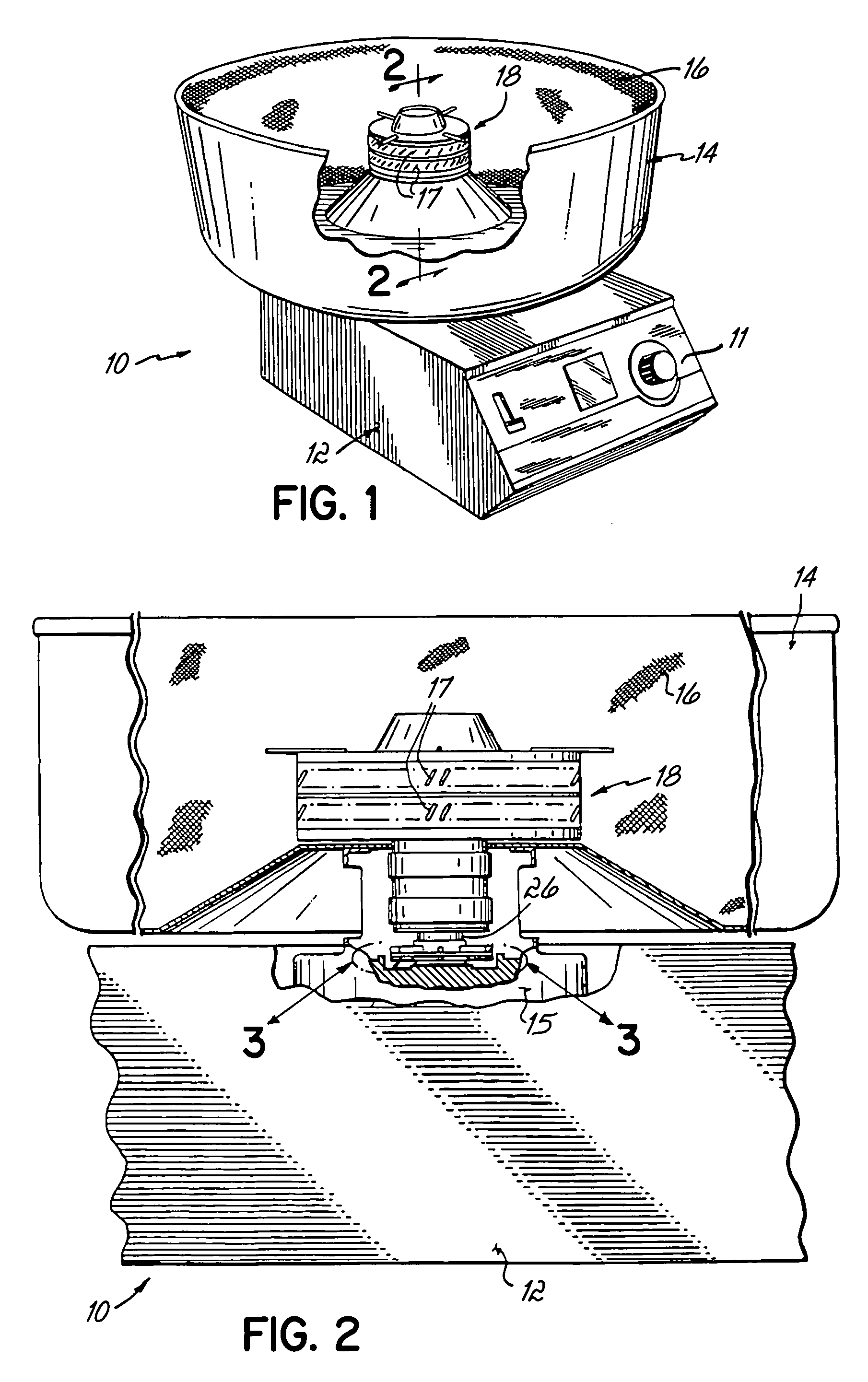
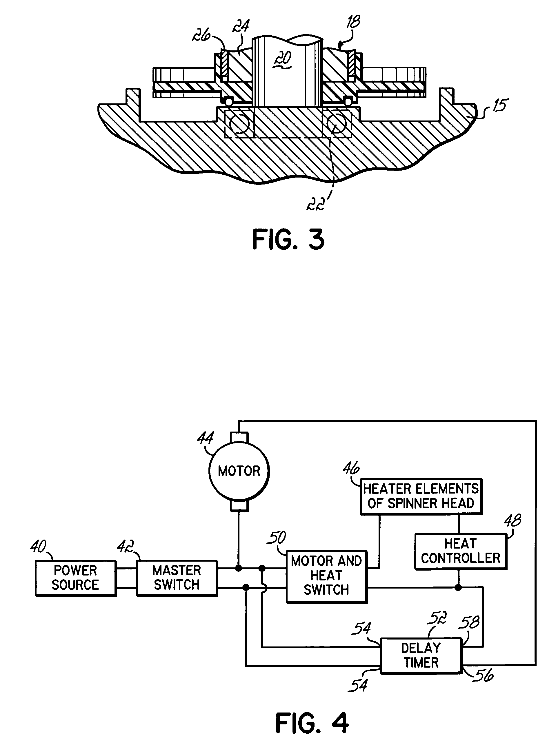
[0017]With reference first to FIG. 1 there is shown a cotton candy machine 10 of one type with which the invention may be used. The machine 10 includes a base 12 on which a basket or bowl 14 is mounted. The basket 14 includes a mesh insert 16 for catching cotton candy (not shown) as the cotton candy is formed. Referring to FIGS. 1-3, a motor shown diagrammatically at 15 supports a rotatable spinner head 18. Spinner head 18 includes a heating element or the like (not shown) to melt granular sugar which is introduced thereinto. In operation rotating spinner head 18 causes melted sugar to be thrown out of or otherwise ejected from slots 17 in the form of filaments. The sugar filaments collect on the mesh insert 16. The details of spinner head 18 are known generally to those skilled in the art and are not described or shown in great detail herein.

[0018]The lower end of spinner head 18 is mounted to a rotatable shaft 20. That shaft 20 is supported by bearings shown diagrammatically at 22...


PUM

PropertyMeasurementUnit
time periodaaaaaaaaaa
temperaturesaaaaaaaaaa

Abstract

Within a cotton candy machine a delay-on-break delay timer is used to delay the de-energization of the spinner-head motor for a predetermined period of time after the heater elements are turned off. Thus, while the heater elements are cooling down, the motor and spinner head continue to rotate. Once the heater elements are cooled to the point where they cannot melt or burn the sugar, then the motor can be de-energized and the spinner head allowed to stop.

Description

FIELD OF THE INVENTION[0001]This invention relates generally to cotton candy machines, and more particularly to an improvement in cotton candy machines for preventing sugar from burning in the spinner head.BACKGROUND OF THE INVENTION[0002]Machines for spinning granular sugar into sugar filaments or so-called cotton candy are known and have been employed for some time to produce cotton candy. A typical cotton candy machine has a base which houses a motor which drives a rotatable shaft to which a spinner head is mounted. Bearings rotatably support the rotating shaft within the motor. Granular sugar is introduced into the spinner head which includes heating elements and the like for melting the granular sugar. The rotation of the spinner head causes the melted granular sugar to be spun or slung out of holes or slots in the spinner head and onto the inner surface of a bowl or basket mounted to the base of the cotton candy machine. The sugar filaments adhered to the basket may then be tr...

Claims


Application Information

Patent Timeline
Patent Type & Authority Patents(United States)
IPC IPC(8): A23G3/00A23G3/10
CPCA23G3/10
Inventor RYAN, JOHN J.
Owner GOLD MEDAL PRODS
Why Eureka
Try Eureka