Pulse width modulation method and apparatus

a pulse width and modulation method technology, applied in pulse manipulation, pulse generators, pulse techniques, etc., can solve the problem of not being able to realize the above ideal modulation scheme by the conventional single-side modulation scheme, and achieve the effect of high-resolution pulse width modulation and less cos

Inactive Publication Date: 2007-11-27
DIGIAN TECH
View PDF5 Cites 30 Cited by
  • Summary
  • Abstract
  • Description
  • Claims
  • Application Information

AI Technical Summary

Benefits of technology

[0010]In light of the aforementioned disadvantages of the conventional technology, it is an object of the present invention to provide a pulse width modulation method and apparatus that can maintain the advantage of the single-side modulation scheme and is able to overcome or reduce the disadvantage thereof.
[0013]The pulse width modulation method and apparatus according to the present invention have the following practical advantages. That is, it is possible to provide a large number of output pulse values (patterns) like the conventional single-side modulation scheme, while the centers of energy of the output pulses is averaged in time to be equal to the center of the PWM period, thereby making it applicable to high resolution pulse width modulation. Additionally, means for achieving the above objectives are simple and less expensive because 2 kinds of output pulse generators are switched in time or the time when the output pulses are generated in the PWM period is shifted.

Problems solved by technology

However, it was impossible to realize the above ideal modulation scheme by the conventional single-side modulation scheme or the both-side modulation scheme, because they have disadvantages of shifting the centers of energy of the output pulses from the center of the clock period and limited values of the output pulses, respectively.

Method used


Image

  • Pulse width modulation method and apparatus
  • Pulse width modulation method and apparatus
  • Pulse width modulation method and apparatus

Examples


Embodiment Construction

[0022]Now, the construction and the operation of the pulse width modulation method and apparatus according to the preferred embodiment of the present invention will be described in detail by making reference to the accompanying drawings.

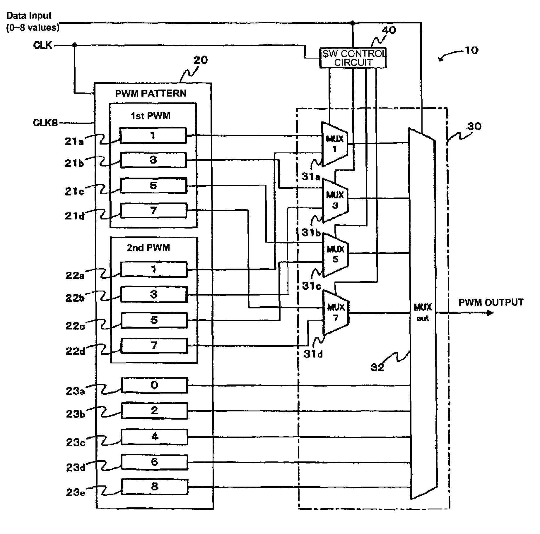
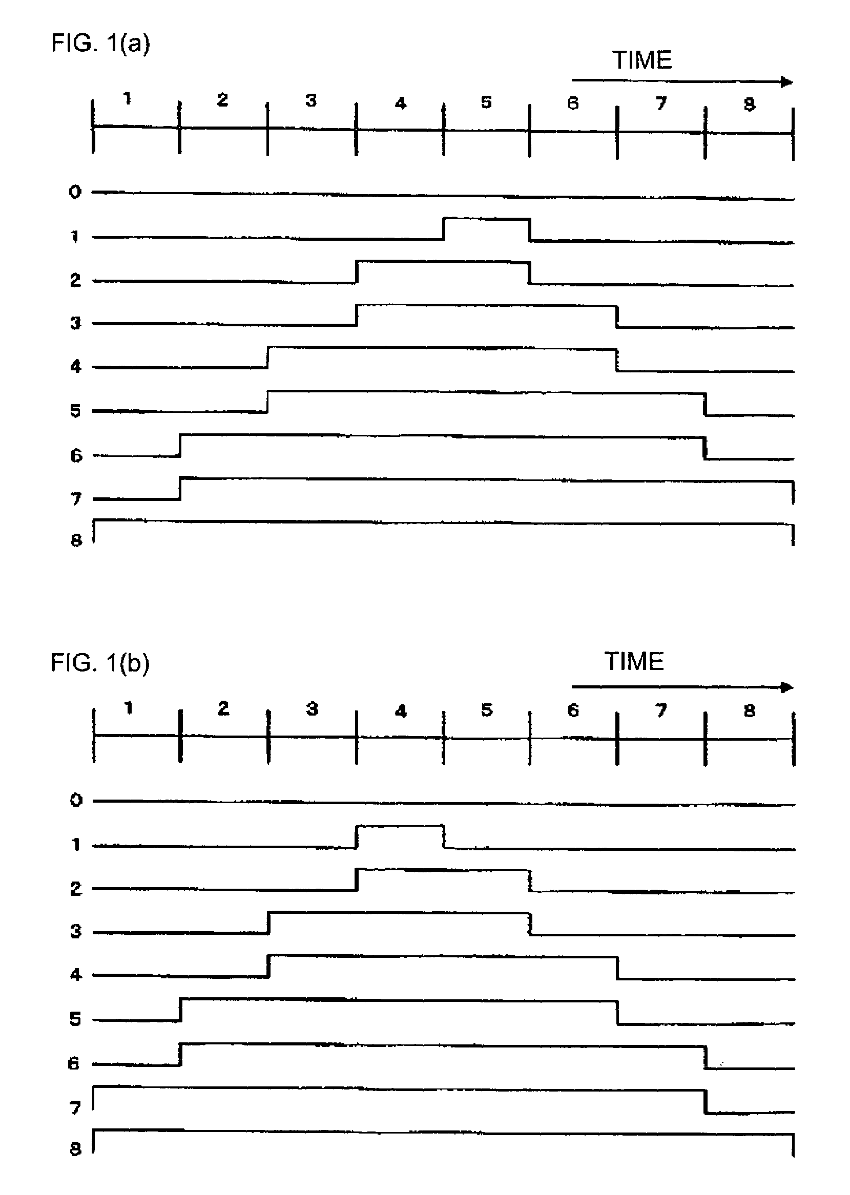
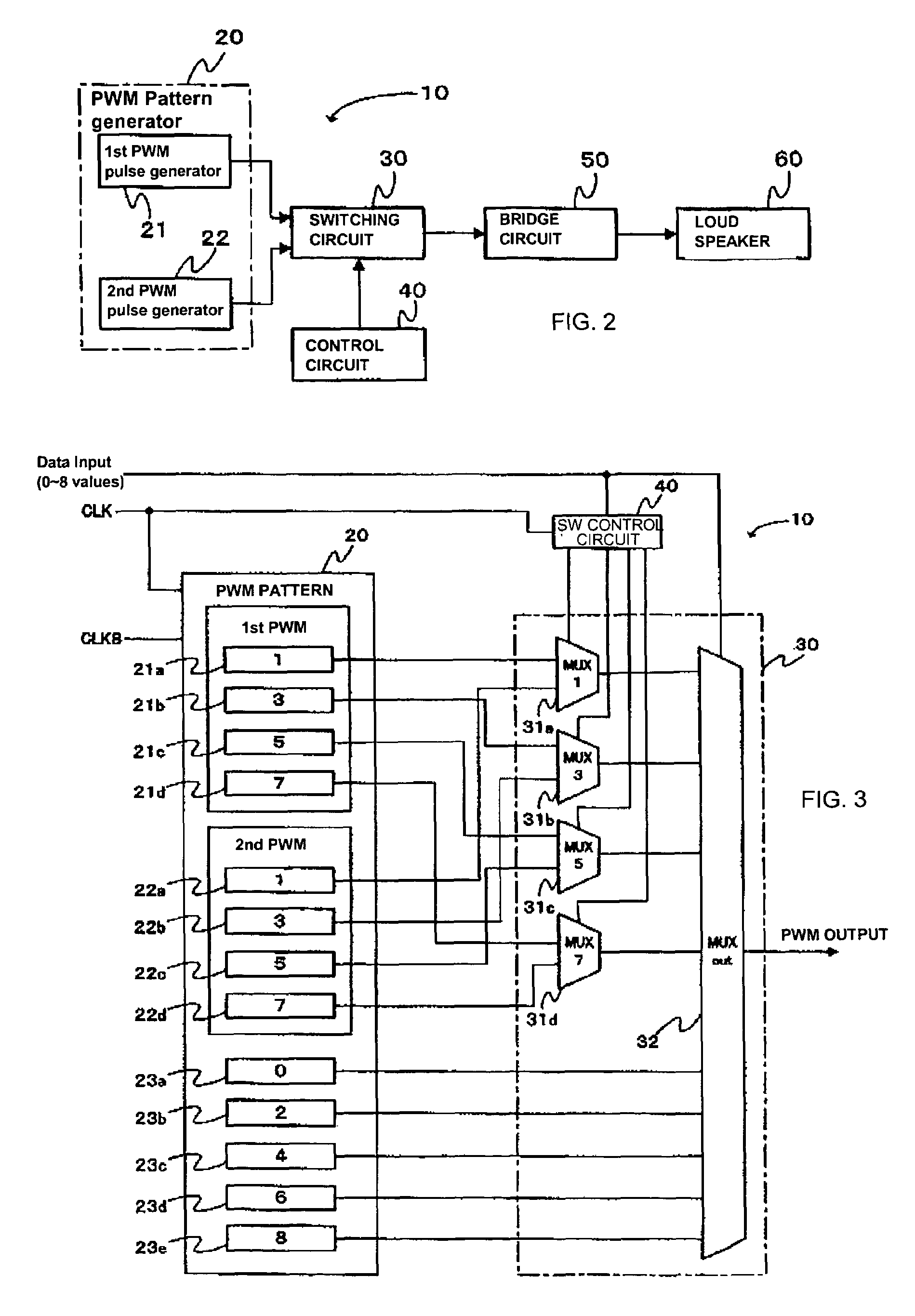
[0023]FIG. 1 is an illustration of the pulse width modulation method and apparatus according to the present invention. FIG. 1(A) shows first pulse width modulated outputs (referred to as first PWM pulses below), while FIG. 1(B) shows second pulse width modulated outputs (referred to as second PWM pulses below).

[0024]In FIGS. 1(A) and (B), the horizontal axes represent time, or 1 pulse width modulation (PWM) period of the reference clock. In this particular embodiment, 8 reference clocks, or first˜eighth reference clocks constitute 1 pulse width modulation period (PWM period). Firstly, reference is made to FIG. 1(A) to describe the aforementioned first PWM pulses. In the 1 PWM period, in case of a pattern “0” of the output pulse, the output remains “L...


PUM


Abstract

Disclosed is a pulse width modulation method and apparatus capable of expressing as many values as possible in a pulse width modulation (PWM) period, while maintaining the center of pulse energy substantially equal to the center of the PWM period. For this end, prepared is the PWM pattern generator 20 including 2 kinds of PWM pulse generator 21 and 22 for generating pulses having the pulse width of 0˜N times of the reference clock period in 1 PWM period corresponding to a predetermined number N of the reference clock period. The PWM pulse generators 21 and 22 are properly switched by the switching circuit 30 under control of the control circuit 40 for performing time averaging process so that the centers of energy of the output pulses is substantially equal to the center of the PWM period.

Description

FIELD OF INVENTION[0001]The present invention relates to a pulse width modulation method and apparatus, more specifically to a pulse width modulation method and apparatus for a driver control circuit that drives a bridge configuration driver circuit in a class-D amplifier or the like.BACKGROUND ART[0002]Generally, an audio output amplifier for power amplifying an audio signal to drive a load such as, for example, a speaker or the like employs a class-D amplifier, wherein 4 switching devices such as, for example, CMOS transistors or the like are connected in a bridge configuration for improving power efficiency.[0003]The 4 switching devices constituting the bridge section perform pulse width modulation in response to the input audio signal using a pulse width modulator (PWM) for ON / OFF controlling the bridge control circuit by the pulse width modulated signal. The ON / OFF control of the switching devices drives highly efficiently the load such as the speaker or the like.[0004]There ar...

Claims


Application Information

Patent Timeline
Patent Type & Authority Patents(United States)
IPC IPC(8): H03K7/00H02M1/12H03F3/217H03K7/08H04L25/49
CPCH03F3/217H03K7/08H03F2200/351
Inventor SHINOHARA, YOSHIAKI
Owner DIGIAN TECH
Why Eureka
Try Eureka