Clearance sweep test

a technology of sweep test and clearance, applied in the direction of magnetic recording, data recording, instruments, etc., can solve the problems of degrading the reliability of the head-disk interface, unsatisfactory wear of lubricant,

Inactive Publication Date: 2007-11-27
SAMSUNG ELECTRONICS CO LTD
View PDF4 Cites 11 Cited by
  • Summary
  • Abstract
  • Description
  • Claims
  • Application Information

AI Technical Summary

Problems solved by technology

During the calibration technique the head may drag along the disk and create undesirable wear of the lubricant. FIG. 1 shows a disk track with a series of modulated wear patterns 1 caused by a calibration technique.
The modulated wear pattern can degrade head-disk interface reliability.

Method used


Image

  • Clearance sweep test
  • Clearance sweep test
  • Clearance sweep test

Examples


Embodiment Construction

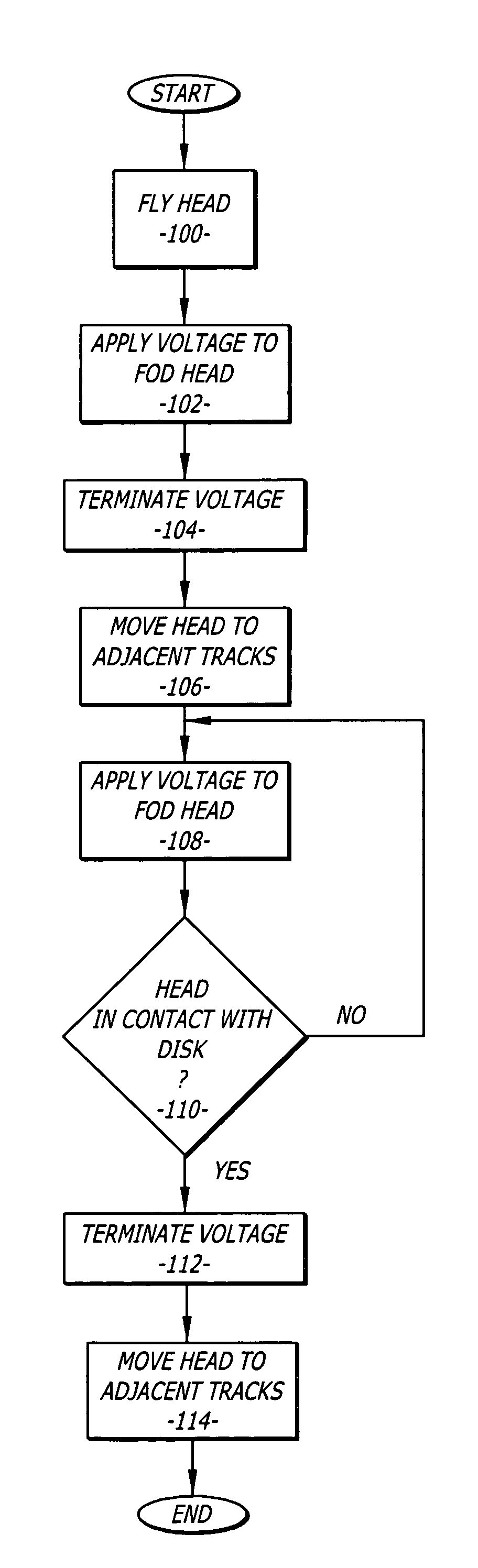
[0017]Disclosed is a calibration method for a fly on demand head of a hard disk drive. The method includes the steps of flying a head over a test track of a disk that is covered with a lubricant. A voltage is applied to a heating element of the head to move the head closer to the disk. The fly height of the head is then determined. The voltage can be incrementally varied until the head makes contact with the disk. This sequence can cause a modulated wear pattern in the lubricant of the disk. The voltage is terminated and the head is allowed to fly over the test track. The head is also moved to adjacent tracks on either side of the test track. A pressure gradient of the flying head moves the lubricant about the disk to mitigate the modulated wear pattern.

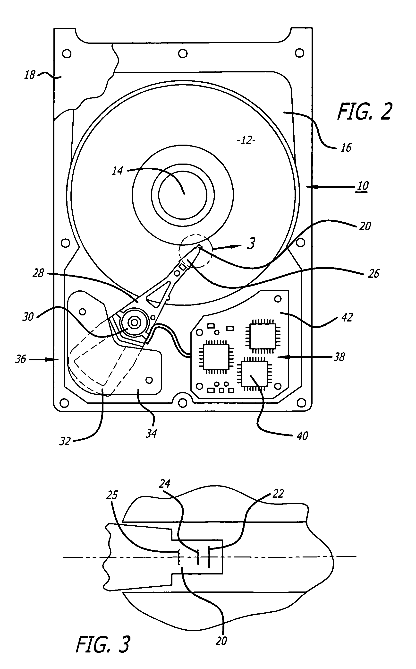
[0018]Referring to the drawings more particularly by reference numbers, FIG. 2 shows an embodiment of a hard disk drive 10 of the present invention. The disk drive 10 may include one or more magnetic disks 12 that are rotated by a sp...


PUM

PropertyMeasurementUnit
timeaaaaaaaaaa
voltagesaaaaaaaaaa
frequencyaaaaaaaaaa

Abstract

A calibration method for a fly on demand head of a hard disk drive. The method includes the steps of flying a head over a test track of a disk that is covered with a lubricant. A voltage is applied to a heating element of the head to move the head closer to the disk. The fly height of the head is then determined. The voltage can be incrementally varied until the head makes contact with the disk. This sequence can cause a modulated wear pattern in the lubricant of the disk. The voltage is terminated and the head is allowed to fly over the test track. The head is also moved to adjacent tracks on either side of the test track. A pressure gradient of the flying head moves the lubricant about the disk to mitigate the modulated wear pattern.

Description

BACKGROUND OF THE INVENTION[0001]1. Field of the Invention[0002]The present invention relates to hard disk drives and a method for minimizing wear patterns created by contact between a head and a disk of the drive.[0003]2. Background Information[0004]Hard disk drives contain a plurality of magnetic heads that are coupled to rotating disks. The heads write and read information by magnetizing and sensing the magnetic fields of the disk surfaces. Each head is attached to a flexure arm to create a subassembly commonly referred to as a head gimbal assembly (“HGA”). The HGA's are suspended from an actuator arm. The actuator arm has a voice coil motor that can move the heads across the surfaces of the disks.[0005]The disks are rotated by a spindle motor of the drive. Rotation of the disks creates an air flow within the disk drive. Each head has an air bearing surface that cooperates with the air flow to create an air bearing between the head and the adjacent disk surface. The air bearing e...

Claims


Application Information

Patent Timeline
Patent Type & Authority Patents(United States)
IPC IPC(8): G11B15/18
CPCG11B5/3169G11B5/6005G11B5/455G11B5/40
Inventor CHEN, CHAO YUANSUN, SHUYUPHAM, HOALEE, SANG
Owner SAMSUNG ELECTRONICS CO LTD
Why Eureka
Try Eureka