Methods and systems for reverse-circulation cementing in subterranean formations

a technology of reverse circulation cementing and subterranean formations, applied in the directions of sealing/packing, survey, borehole/well accessories, etc., to achieve the effect of facilitating the determination of the cement composition volum

Active Publication Date: 2007-12-04
HALLIBURTON ENERGY SERVICES INC
View PDF146 Cites 40 Cited by
  • Summary
  • Abstract
  • Description
  • Claims
  • Application Information

AI Technical Summary

Benefits of technology

[0010]Another example of a system of the present invention is a system for cementing casing in a well bore comprising: a casing inserted into the well bore and defining an annulus therebetween, the casing having an inner diameter; a circulation fluid for flowing into the well bore, the circulation fluid having a leading edge that comprises a marker, and having a trailing edge, wherein the flow of the circulation fluid and marker into the well bore facilitates determination of a volume of cement composition sufficient to fill a desired portion of the annulus; a cement composition for flowing into at least a portion of the annulus, the cement composition having a leading edge in fluid communication with the trailing edge of the circulation fluid; and a marker detector in fluid communication with fluid passing through the inner diameter of the casing.

Problems solved by technology

This may be problematic because it may prevent the subsequent placement of tools (e.g., perforating equipment) adjacent the hydrocarbon-bearing zone, which may prevent the perforation of the zone and subsequent production of hydrocarbons therefrom, unless the excess cement is drilled out.

Method used


Image

  • Methods and systems for reverse-circulation cementing in subterranean formations
  • Methods and systems for reverse-circulation cementing in subterranean formations
  • Methods and systems for reverse-circulation cementing in subterranean formations

Examples


example

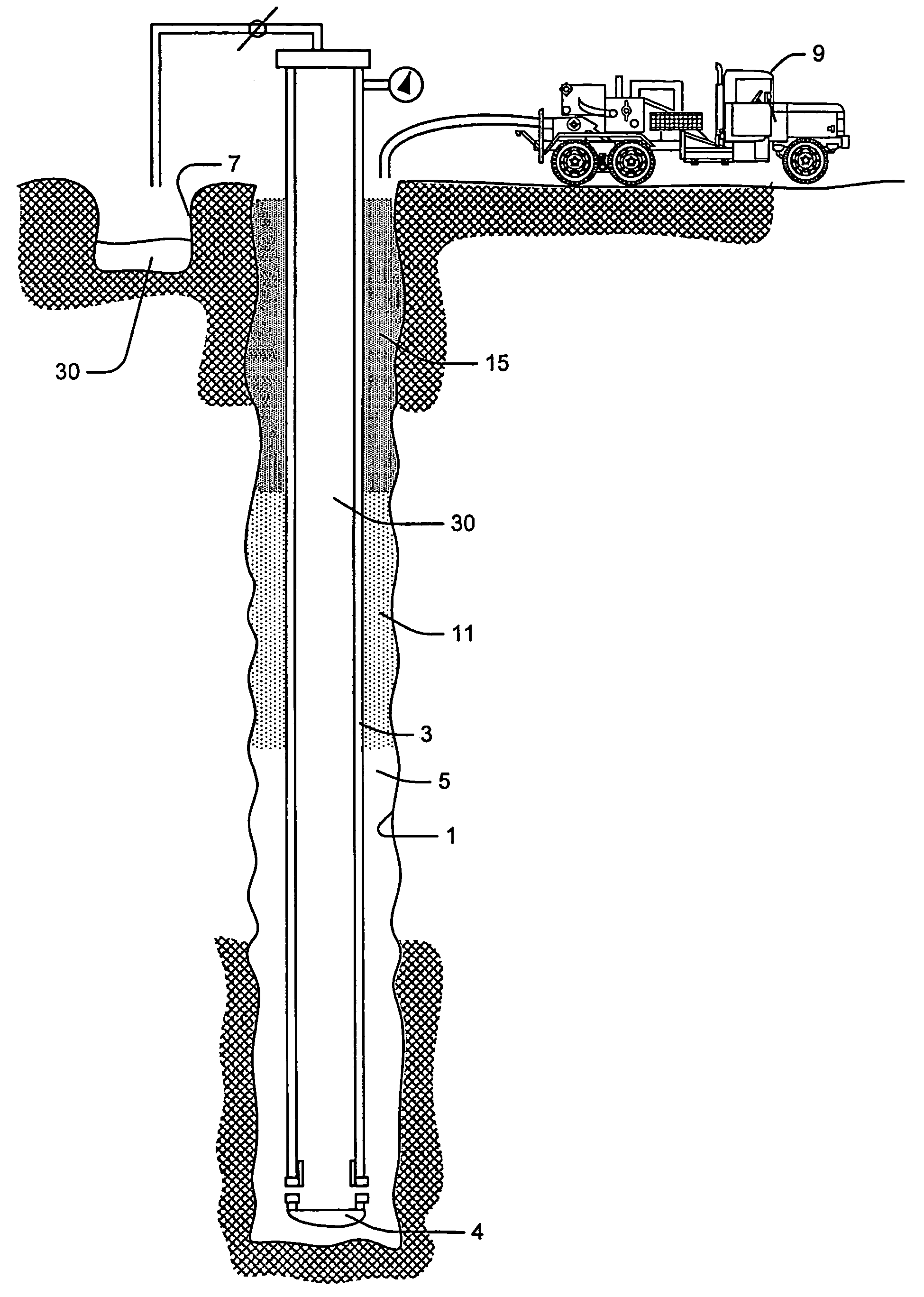
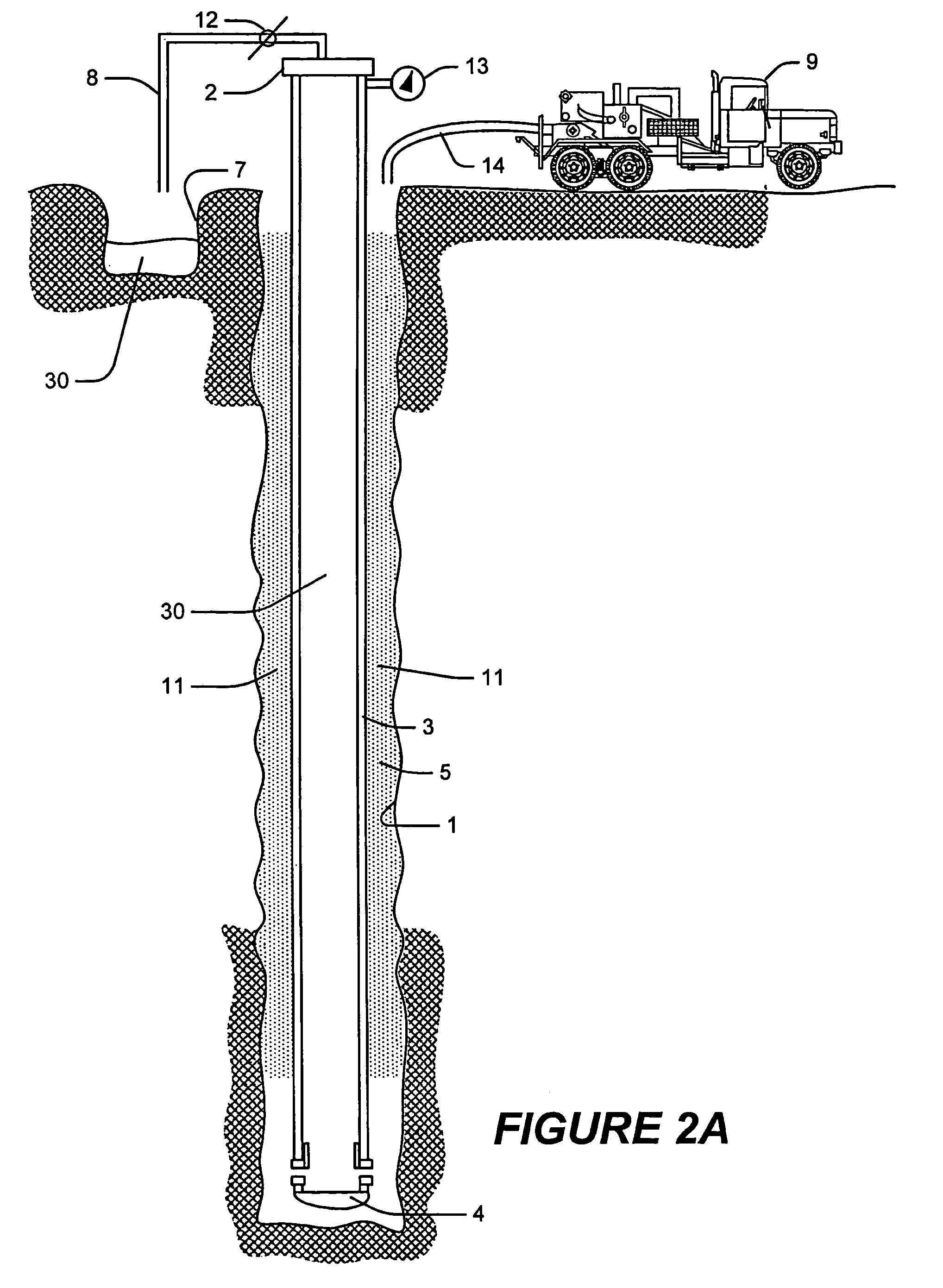
[0029]For example, assume that casing 3 has a length of 2,000 feet, and an internal diameter of 5 inches. Assume further that the desired length of casing 3 to be cemented is 2,000 feet. Accordingly, the radius of casing 3 will be 2.5 inches. Thus, Vtot=H πr2=[(2000 feet)(3.1416)((2.5 inch)2 / 144)] / (5.614583)=48.6 barrels. Further assume that the desired cement composition 15 has a density of 80 lbs / ft3, that circulation fluid 30 has a density of 65 lbs / ft3, and that the desired equilibrium fluid 11 has a density of 100 lbs / ft3. Accordingly, applying EQUATION 2, Vef=Vtot(ρcc15−ρcf30) / (ρef11−ρcf30)=48.6 barrels (80 lbs / ft3−65 lbs / ft3) / (100 lbs / ft3−65 lbs / ft3)=20.8 barrels. Thus, in this example, 20.8 barrels of equilibrium fluid 11 would be required for use in order to ensure that the pressure displayed by pressure indicator 13 read zero when the leading edge of cement composition 15 reached casing shoe 4.

[0030]Where a relatively heavy equilibrium fluid 11 is used, it may be injected ...


PUM


Abstract

Methods and systems for reverse-circulation cementing in subterranean formations are provided. An example of a method is a method of cementing casing in a subterranean well bore, comprising inserting a casing into the well bore, the casing comprising a casing shoe; equipping the casing with a well head, and a casing inner diameter pressure indicator; flowing an equilibrium fluid into the well bore; flowing a cement composition into the well bore after the equilibrium fluid; determining from the well-bore pressure indicator when the well bore pressure has reached a desired value; discontinuing the flow of cement composition into the well bore upon determining that the well bore pressure has reached a desired value; and permitting the cement composition to set in the subterranean formation. Examples of systems include systems for cementing casing in a well bore.

Description

BACKGROUND OF THE PRESENT INVENTION[0001]The present invention relates to subterranean cementing operations, and more particularly, to methods and systems for reverse-circulation cementing in subterranean formations.[0002]Hydraulic cement compositions commonly are utilized in subterranean operations, particularly subterranean well completion and remedial operations. For example, hydraulic cement compositions are used in primary cementing operations whereby pipe strings, such as casings and liners, are cemented in well bores. In performing primary cementing, hydraulic cement compositions commonly are pumped into an annular space between the walls of a well bore and the exterior surface of a pipe string disposed therein. The cement composition is permitted to set in the annular space, thereby forming therein an annular sheath of hardened, substantially impermeable cement that substantially supports and positions the pipe string in the well bore, and that bonds the exterior surface of ...

Claims


Application Information

Patent Timeline
Patent Type & Authority Patents(United States)
IPC IPC(8): E21B33/14E21B33/16E21B47/06
CPCE21B47/0005E21B33/14E21B47/005
Inventor BADALAMENTI, ANTHONY M.BLANCHARD, KARL W.CROWDER, MICHAEL G.FAUL, RONALD R.GRIFFITH, JAMES EROGERS, HENRY E.TURTON, SIMON
Owner HALLIBURTON ENERGY SERVICES INC
Why Eureka
Try Eureka