
Variable aerosol nozzle

a variable-size, aerosol technology, applied in the direction of burners, combustion types, combustion processes, etc., can solve the problems of difficulty and problems, appearance and surface texture cannot be achieved, etc., and achieve the effect of simple and efficient manner

Inactive Publication Date: 2007-12-04
OSMEGEN
View PDF10 Cites 28 Cited by
  • Summary
  • Abstract
  • Description
  • Claims
  • Application Information

AI Technical Summary

Benefits of technology

[0009]In accordance with embodiments of the invention, an object of an embodiment of the present invention is to provide an apparatus with a specialized nozzle that can provide spray patterns of varying textures in a simple and efficient manner.
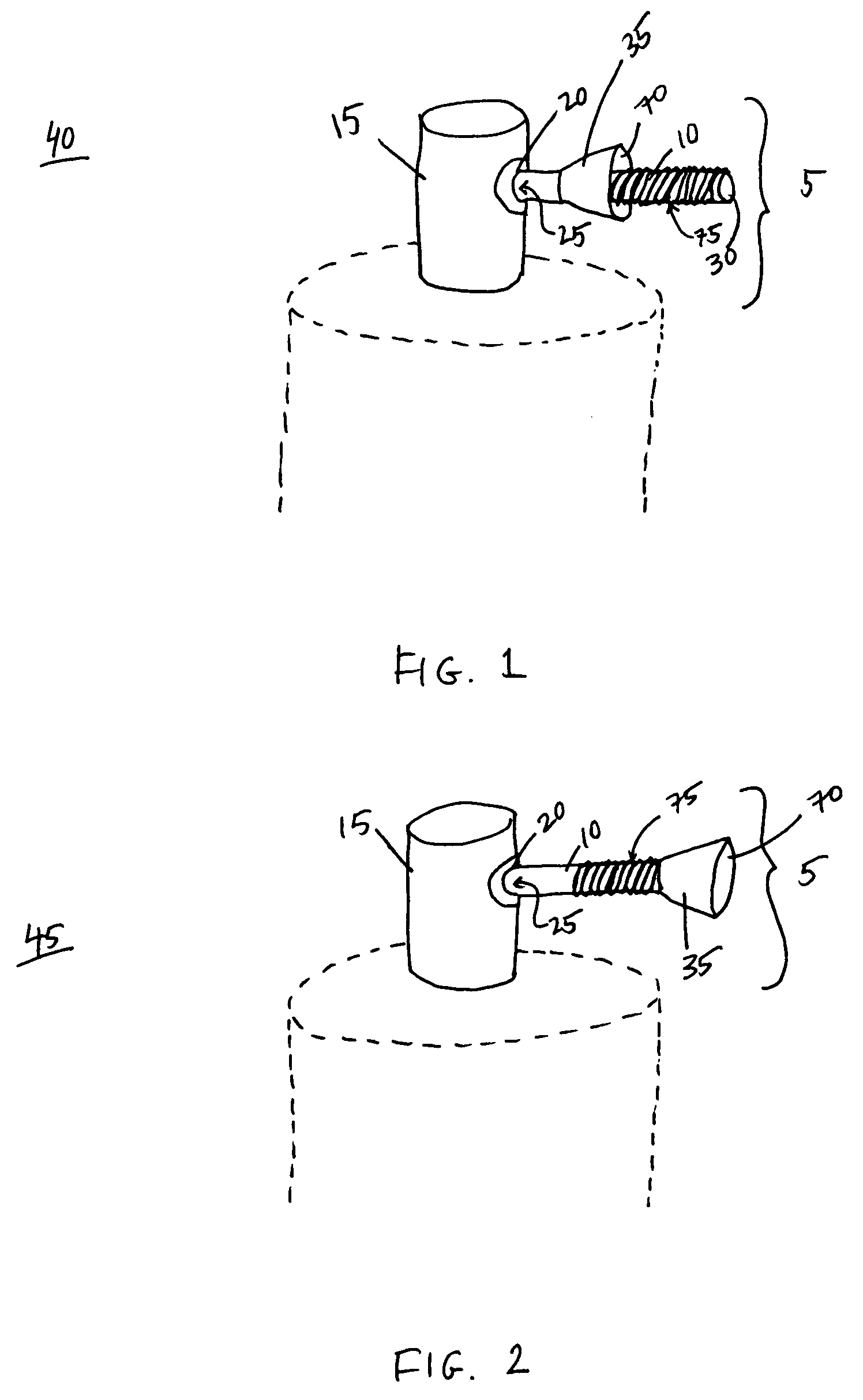
[0010]In an embodiment, there is provided a nozzle having an elongated passageway that extends from the nozzle that serves as an extension of the nozzle. Slidably attached to this elongated passageway is a generally cone-shaped member which is adapted to slide from a first position to a second position interchangeably. For example, the generally cone-shaped member may be slidably attached by screwing threads on the inside of the cone-shaped member and on the outside of the elongated passageway that allow the cone-shaped member to swivel up and down the elongated passageway. When the cone member is in the first position, the cone member is located closer to the nozzle. When the cone member is in the second position, the cone member is located at the end of the elongated passageway, farthest away from the nozzle. In the first position, the sprayable material contained in the aerosol apparatus will be dispensed according to the sole orifice of the single elongated passageway. The spray will be smaller in scope and more concentrated with finer particles. In the second position, the cone member is located at the end of the elongated passageway and thus expands the trajectory of the spray as it exits the single orifice of the single elongated passageway. The second position thus facilitates a broader spray which is less concentrated with coarser particles. In embodiments, the slidably attached member is generally flared.

Problems solved by technology

Such an appearance and surface texture cannot be attained through the use of smoothing tools or patch tools once the patch material has been applied to the damaged or repaired area.
Therefore, difficulties and problems have been encountered that stem largely from the fact that the use and application of conventional patching materials on the repairs of such surfaces leaves a surface texture that does not match the surrounding area and is noticeable after the repair has been completed.

Method used


Image

  • Variable aerosol nozzle
  • Variable aerosol nozzle
  • Variable aerosol nozzle

Examples


Embodiment Construction

[0016]In the following description, reference is made to the accompanying drawings which form a part hereof and which illustrate several embodiments of the present inventions. It is understood that other embodiments may be utilized and structural and operational changes may be made without departing from the scope of the present inventions.

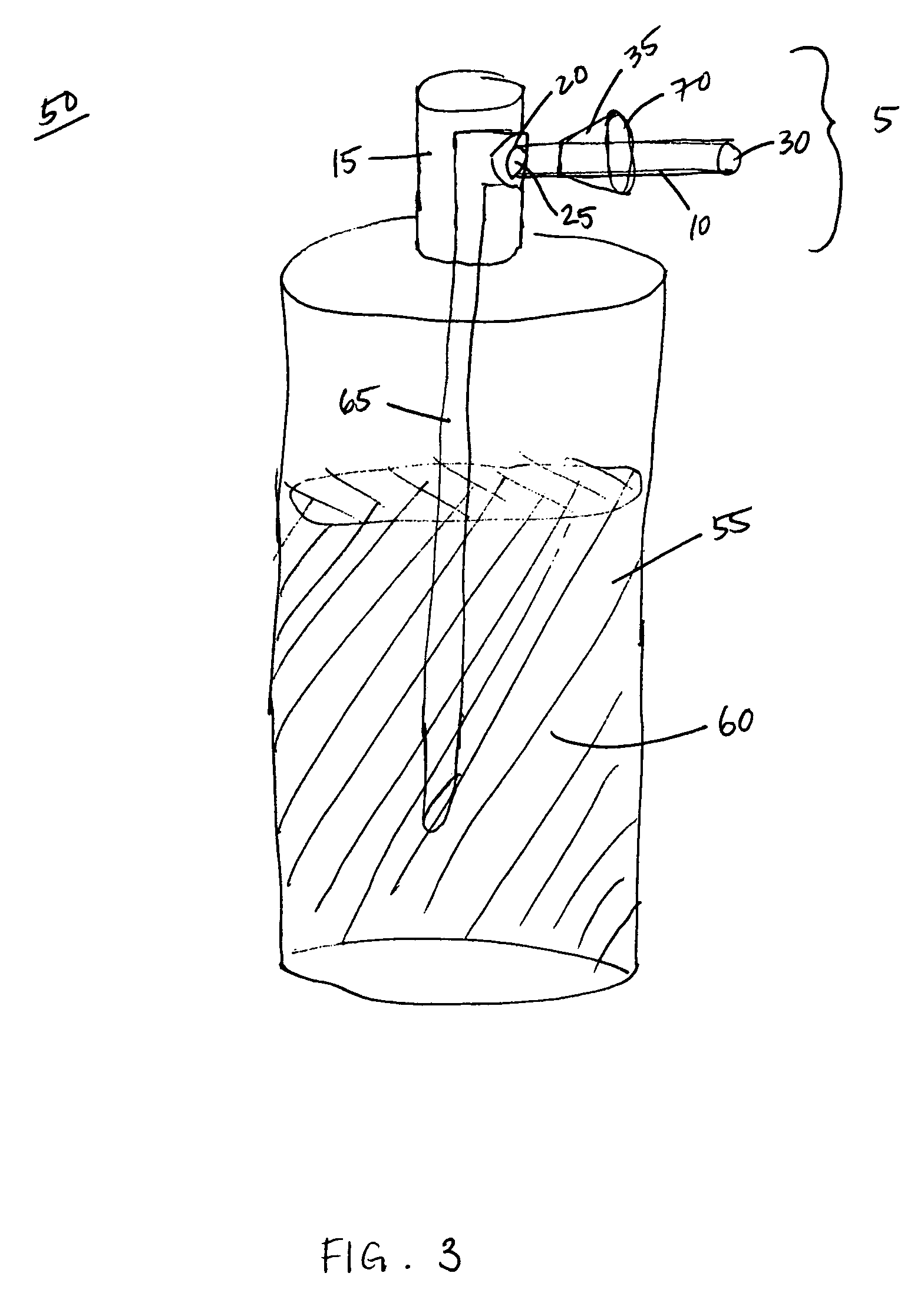
[0017]As shown in FIG. 1, there is provided a nozzle assembly 5 of an aerosol apparatus for spraying variable textures. The nozzle assembly 5 has a single elongated passageway 10 that extends from an actuator 15. The actuator 15 includes an aperture 20 forming a nozzle opening 25 to which the elongated passageway 10 is connected and from which the elongated passageway 10 serves as an extension. The elongated passageway 10 has a single orifice 30 from which the spray exits. Slidably attached to this elongated passageway 10 is a generally flared or cone-shaped member 35 which is adapted to slide from a first position 40 to a second position 45 inter...


PUM


Abstract

A specialized nozzle assembly that dispenses spray patterns of varying textures, e.g., coarse or fine particles; for use in an aerosol system for applying a spray texture material to a wall or like supporting structure. The nozzle assembly includes an elongated passageway and a generally cone-shaped member attached thereon.

Description

FIELD OF THE INVENTION[0001]1. Field of the Invention[0002]Embodiments of the present invention relate generally to an aerosol system for applying a spray texture material to a wall or like supporting structure. More particularly, embodiments are directed to a nozzle adapted to provide variable spraying of the material so as to dispense spray patterns that may vary in texture, e.g., coarser or finer particles, may be achieved. The system further comprises an aerosol container that holds the pressurized spray texture material. The material is dispensed through a dip tube that connects to a nozzle. The spray texture material exits from the container through the nozzle.[0003]2. Description of Related Art[0004]It has been the conventional practice in the procedure of repairing drywall or other like areas to remove the damaged portion of the surface and subsequently fill any holes, depressions, or the like with a prepared patch material. The patch or replacement material is applied by me...

Claims


Application Information

Patent Timeline
Patent Type & Authority Patents(United States)
IPC IPC(8): B05B1/32
CPCB05B1/12B05B1/28B65D83/14
Inventor WOODS, JOHN R.
Owner OSMEGEN
Learn More