

Relocatable transportable safety crash barrier system
a technology of safety barriers and transportable barriers, applied in the direction of roads, traffic signals, roads, etc., can solve the problems of vehicle breaching the barrier, pedestrians or objects behind the barrier, and the inability to safely absorb impacts
- Summary
- Abstract
- Description
- Claims
- Application Information
AI Technical Summary
Benefits of technology
Problems solved by technology
Method used
Image

Examples
Embodiment Construction
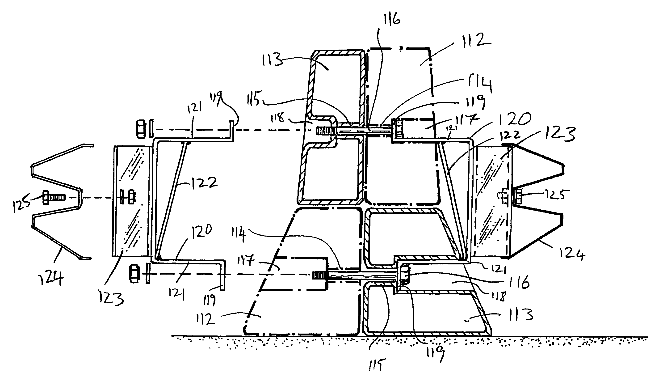
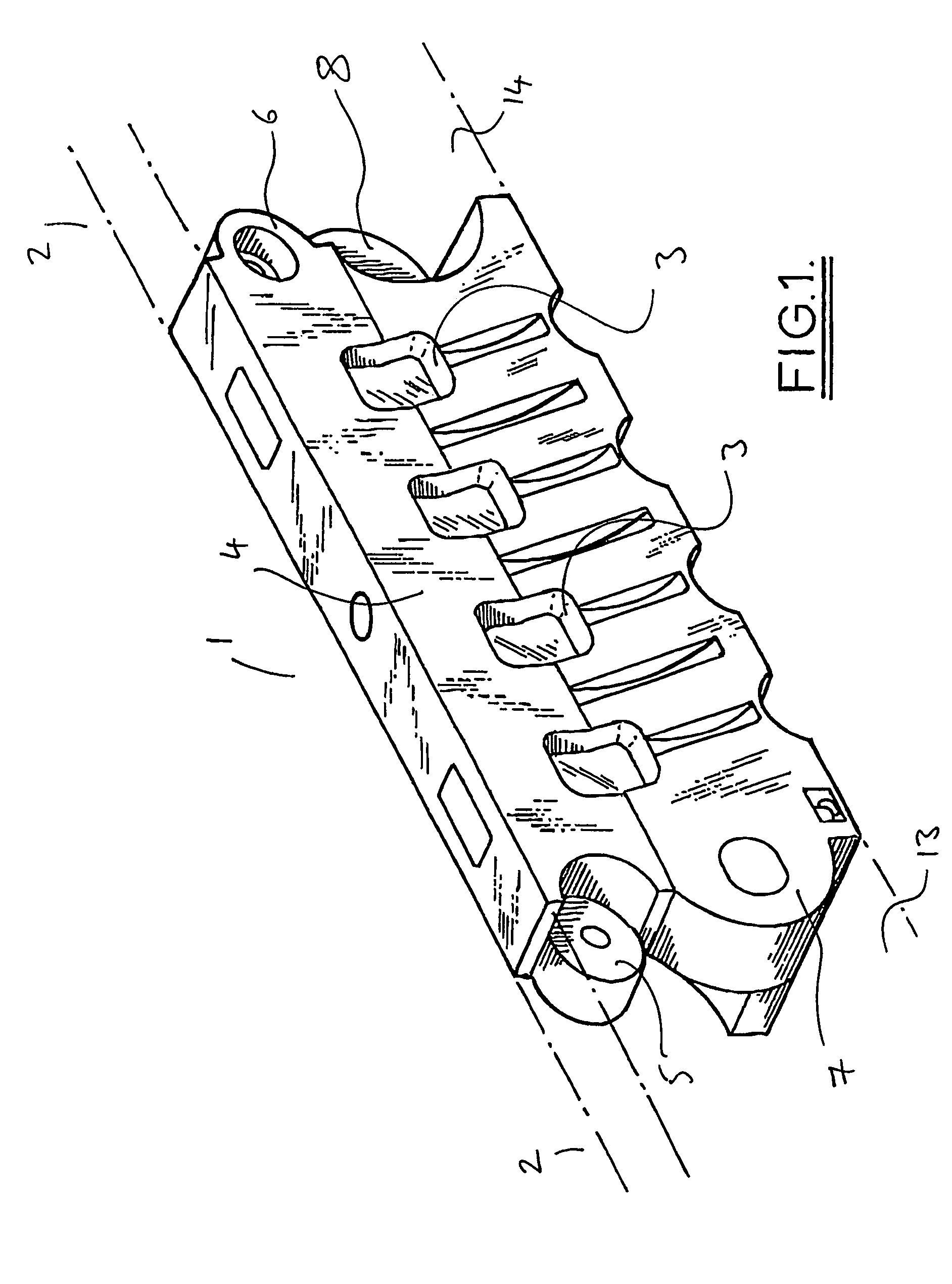
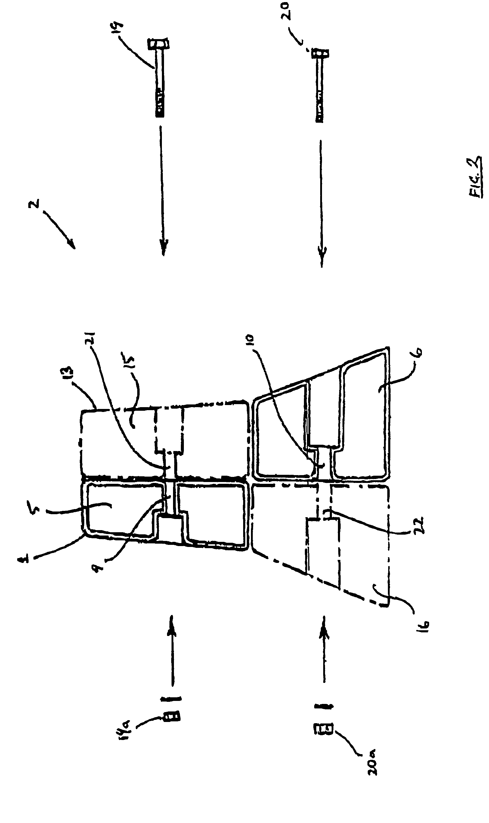
[0010]The relocatable traffic barrier constructed in accordance with the present invention is greatly stiffened against lateral deflections due to vehicle impacts by the crash rail. The greater the number of modules to which a single span of the crash rail is secured, the better this stiffening effect will be. The crash rail or rails may be of known type, such as rolled steel “W” sections made for the purpose or proprietary designed steel sections. In addition to providing an alternative form of construction to existing traffic barriers with crash-resistance, the invention allows easy handling and transport, permitting modules to be brought to site with or without crash rails or the fittings attached and assembled into a continuous barrier by connecting them end-to-end. After attaching the fittings (if not attached to the modules before their connection together) the crash rail itself may be attached and the modules ballasted as necessary by filling with fluid.
[0011]The barrier may ...
PUM
 Abstract
Description
Claims
Application Information