
Split valve for peel-away sheath

a technology of split valve and introducer sheath, which is applied in the field of medical devices, can solve the problems of backflow of blood through the introducer sheath, the placement of the catheter without an introducer sheath, and the limited use of the introducer sheath in vascular applications, so as to restrict any blood backflow and restrict blood backflow

Inactive Publication Date: 2007-12-04
BOSTON SCI SCIMED INC
View PDF13 Cites 19 Cited by
  • Summary
  • Abstract
  • Description
  • Claims
  • Application Information

AI Technical Summary

Benefits of technology

[0008]One valve includes a breakaway distal portion having a lumen therethrough for receiving the introducer sheath proximal region and a proximal portion including two opposed body members movable relative to each other and having facing concave surfaces for receiving a flexible valve sleeve therebetween. The valve body members can have an open position and a closed position, wherein the valve body members move apart relative to each other to reach the open position and move together to reach the closed position. The valve sleeve restricts or prevents fluid backflow through the constricted valve sleeve lumen in the closed position, and allows passage of an inserted catheter while in the open position.
[0010]In one embodiment, the pinch member is disposed midway through the valve body, and the valve body includes a proximal port, even when closed, for admitting a catheter distal end into the closed valve body and into the free, open end of a flexible valve sleeve. In another embodiment, the pinch member is disposed near the proximal end of the valve body, and the valve sleeve includes a portion extending proximally from the valve body. Some embodiments include a recess or guide wire lumen through the pinch member or members, even when closed, to allow for the presence of a guide wire without clamping down on the guide wire surface when the valve body is in the closed position.
[0012]The valve can then be in the closed position, having the guide wire extending through the valve and out the proximal end of the valve. The guide wire, enclosed in the constricted valve sleeve, lies within a guide wire lumen or recess in some valves which allows for tight closure of the valve body. In other valves lacking a special recess, the valve body can still tightly compress the flexible valve sleeve together and about the guide wire, greatly restricting any blood backflow.
[0013]When introduction of a catheter is called for, the catheter distal end can be inserted into the proximal end of the flexible valve sleeve proximal of the closed pinch point. When the valve body is next opened, the catheter distal end substantially occludes the inside of the valve sleeve, substantially restricting blood backflow, even when the valve sleeve is open. The catheter can be advanced through the introducer sheath to the target site.

Problems solved by technology

Introducer sheaths are often used to facilitate the insertion of catheters into body vessels where placement of the catheter without an introducer sheath may present difficulty.
Typical applications do not include insertion of the sheath into blood vessels, where backflow of blood through the sheath can present a problem.
For this reason, introducer sheaths have seen limited use in vascular applications.
If the sheath were not a peel-away sheath, removal over the inserted catheter and proximal catheter manifold could prove difficult.

Method used


Image

  • Split valve for peel-away sheath
  • Split valve for peel-away sheath
  • Split valve for peel-away sheath

Examples


Embodiment Construction

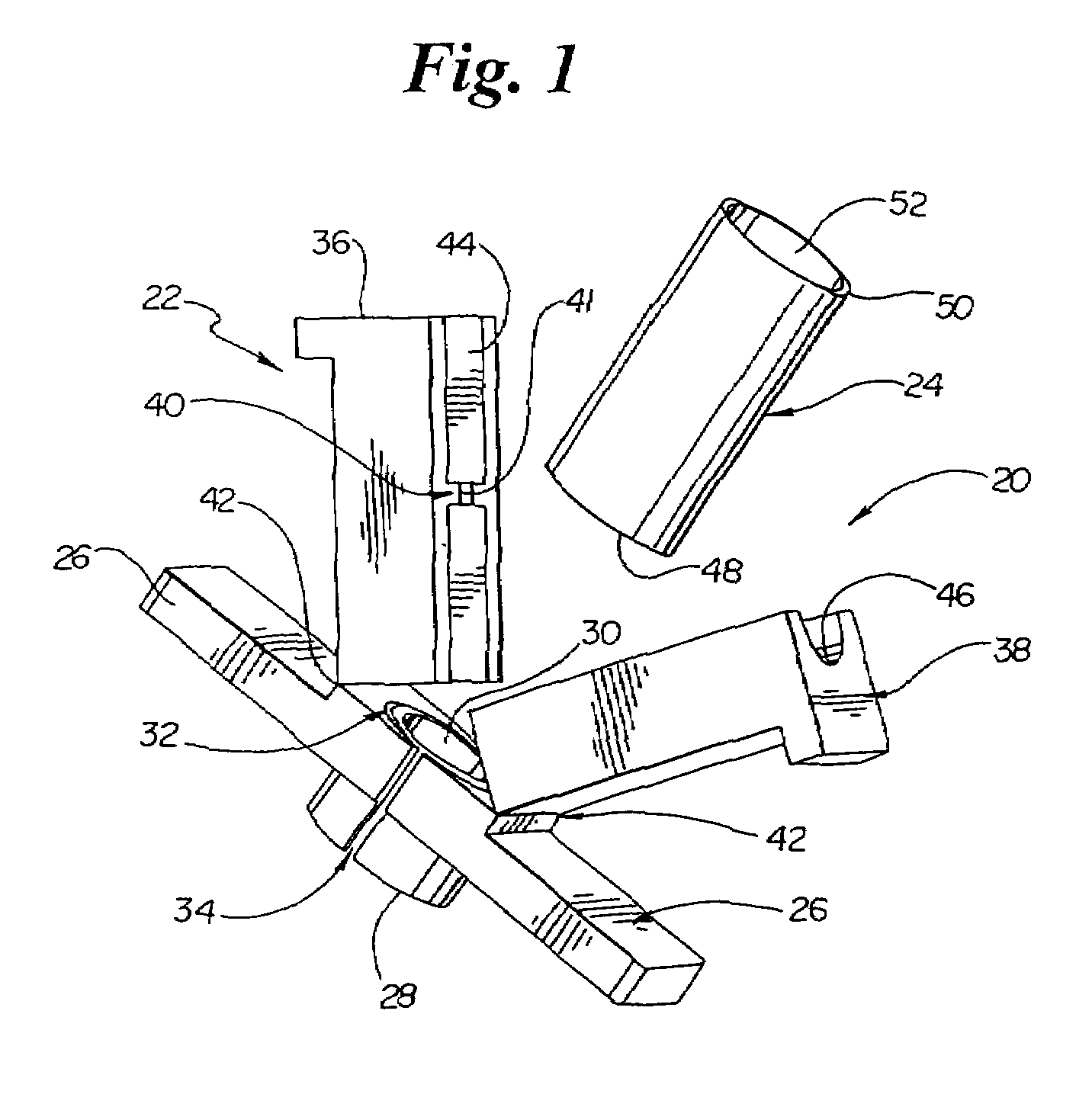
[0021]FIG. 1 illustrates a split valve 20 including a valve body 22 and a valve sleeve 24. Valve 20 includes a distal end 28, a pair of graspable handles or ears 26, a valve sleeve seat 32, and a lumen 30 therethrough. Valve body 22 includes a first moveable member 36, a second moveable member 38, a laterally-oriented pinch member 40, and a pair of snap grooves 34 (only one being visible in FIG. 1). Valve 20 is shown in an open position, having been opened along a pair of hinges 42 lying in a plane substantially transverse to the longitudinal axis of lumen 30. A tubular valve body lumen is formed when the valve body is in a closed position, the lumen being formed by a first concave portion 44 in first body member 36 and a second concave portion 46 in second body member 38.

[0022]Valve sleeve 24 has a distal end 48, a proximal region 50, and lumen 52 therethrough. Valve sleeve 24 is adapted to be received between valve body members 36 and 38. Valve body 22 is preferably formed of a ri...


PUM


Abstract

A breakaway valve body for a peel-away introducer sheath. The valve body can be used in conjunction with a distally coupled peel-away introducer sheath and a proximally coupled flexible valve sleeve for restricting fluid flow from the introducer sheath when the valve body compresses the valve sleeve to a closed position. The valve can include a body scored or weakened to break along a predefined path in response to applied force. The valve preferably includes a first member and a second member movable relative to each other and having a pinch member therebetween for constricting a flexible valve sleeve placed between the first and second members. In one valve, the first and second members are pivotally disposed on hinges to allow the members to open and close about an inserted flexible valve sleeve and to pinch the sleeve with a pinch member. The valve preferably includes a proximal region of valve sleeve extending proximally past the valve pinch member to allow insertion of a catheter distal end into the valve sleeve proximal end while the more distal valve sleeve region is constricted in a closed position. The valve allows insertion of a catheter into the introducer sheath with minimal blood loss. The valve allows easy removal of the sheath from an inserted catheter by snapping the valve and pulling the halves apart, thereby tearing the peel-away sheath away from the catheter.

Description

FIELD OF THE INVENTION[0001]The present invention is generally related to medical devices. More specifically, the present invention is related to introducer sheaths for introducing catheters into the body. The present invention includes a breakaway split valve for restricting fluid flow from a peel-away sheath extending from the body.BACKGROUND OF THE INVENTION[0002]Introducer sheaths are well-known devices which can be used to introduce catheters through body conduits into the human body. Introducer sheaths are often used to facilitate the insertion of catheters into body vessels where placement of the catheter without an introducer sheath may present difficulty. Sheaths are useful where the tract to be traversed is tortuous or obstructed. Introducer sheaths are commonly used in applications where backflow of bodily fluids through the introducer sheath does not present a problem. Typical applications do not include insertion of the sheath into blood vessels, where backflow of blood...

Claims


Application Information

Patent Timeline
IPC IPC(8): A61M5/00A61M25/06A61M39/06
CPCA61M25/0668A61M39/0613A61M2039/062
Inventor CHU, MICHAEL S. H.CHIN, YEM
Owner BOSTON SCI SCIMED INC
Features
  • Generate Ideas
  • Intellectual Property
  • Life Sciences
  • Materials
  • Tech Scout
  • Unparalleled Data Quality
  • Higher Quality Content
  • 60% Fewer Hallucinations
Learn More