
Target surface structure of ball target body scored by microcomputer

A microcomputer and target surface technology, applied to ball games, devices using optical methods, sports accessories, etc., can solve problems such as noise, user distress, accidental injury, etc., and achieve the effect of improving fun

Inactive Publication Date: 2010-10-27
卓钰富
View PDF0 Cites 2 Cited by
  • Summary
  • Abstract
  • Description
  • Claims
  • Application Information

AI Technical Summary

Benefits of technology

This patented technology describes a system where targets made up from sheets called chunks (target areas) are placed onto a curved plate like screen. These screens help crush balls faster than they could naturally roll out. When there're no obstacles near them, it becomes easier to move over these surfaces. A special purpose camera capturing images helps determine if any circles were passed within certain specific locations along their trajectory. By combining multiple layers of material together, this allows for precise detection of different shapes and sizes of balls passing through. Overall, this innovative technical effect provides improved accuracy and efficiency during playback of ballistic events.

Problems solved by technology

This patented technical problem addressed in this patents relates to improving the design of conventional baseball goals used during play without compromising their effectiveness due to these issues such as poor hitting accuracy caused by automatic score systems on targets with multiple imperfections (such as holes) and lacked flexibility needed to allow balls to roll freely while still maintaining accurate impact scores.

Method used


Image

  • Target surface structure of ball target body scored by microcomputer
  • Target surface structure of ball target body scored by microcomputer
  • Target surface structure of ball target body scored by microcomputer

Examples


Embodiment Construction

[0078] In order to enable your examiners to further understand the structure, features and other purposes of the present invention, the attached preferred embodiments are attached with the accompanying drawings in detail as follows. The embodiments illustrated in the accompanying drawings are only used to illustrate the technology of the present invention scheme, but not to limit the present invention.

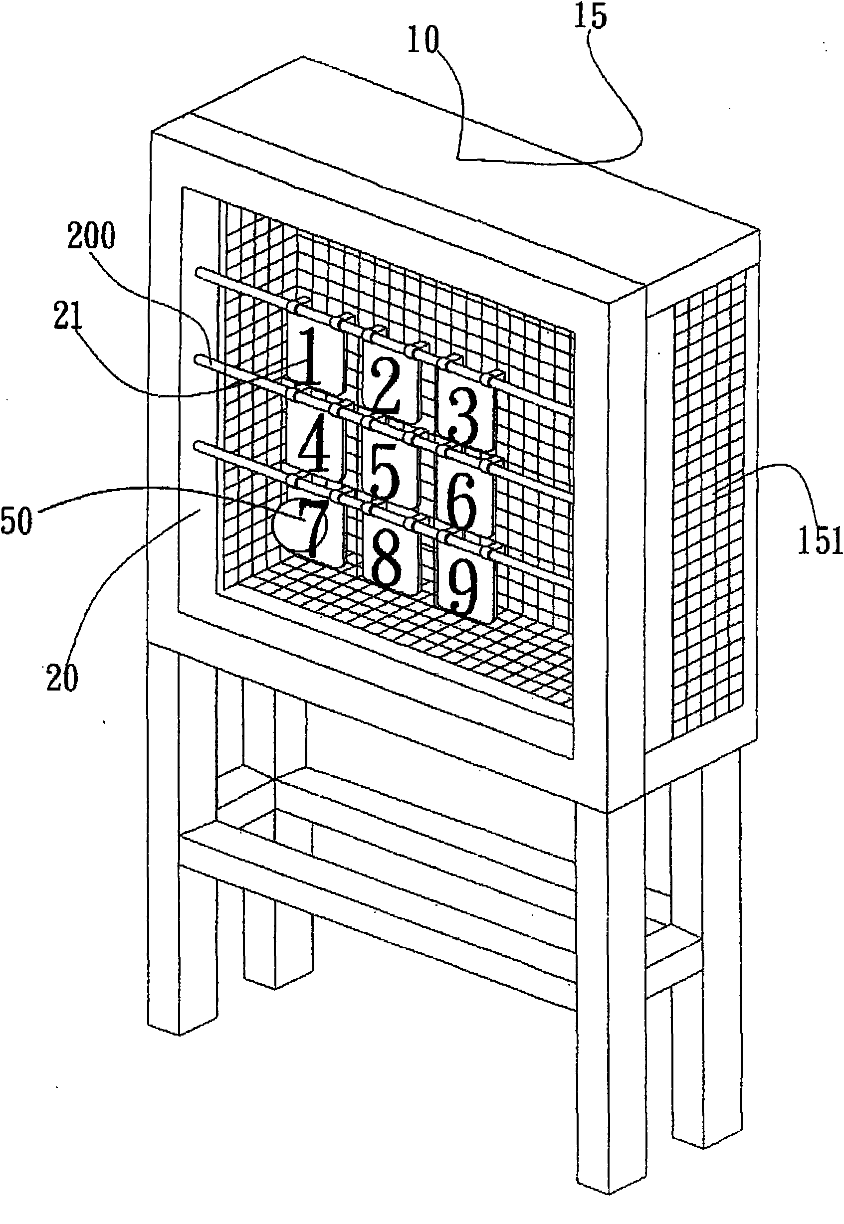
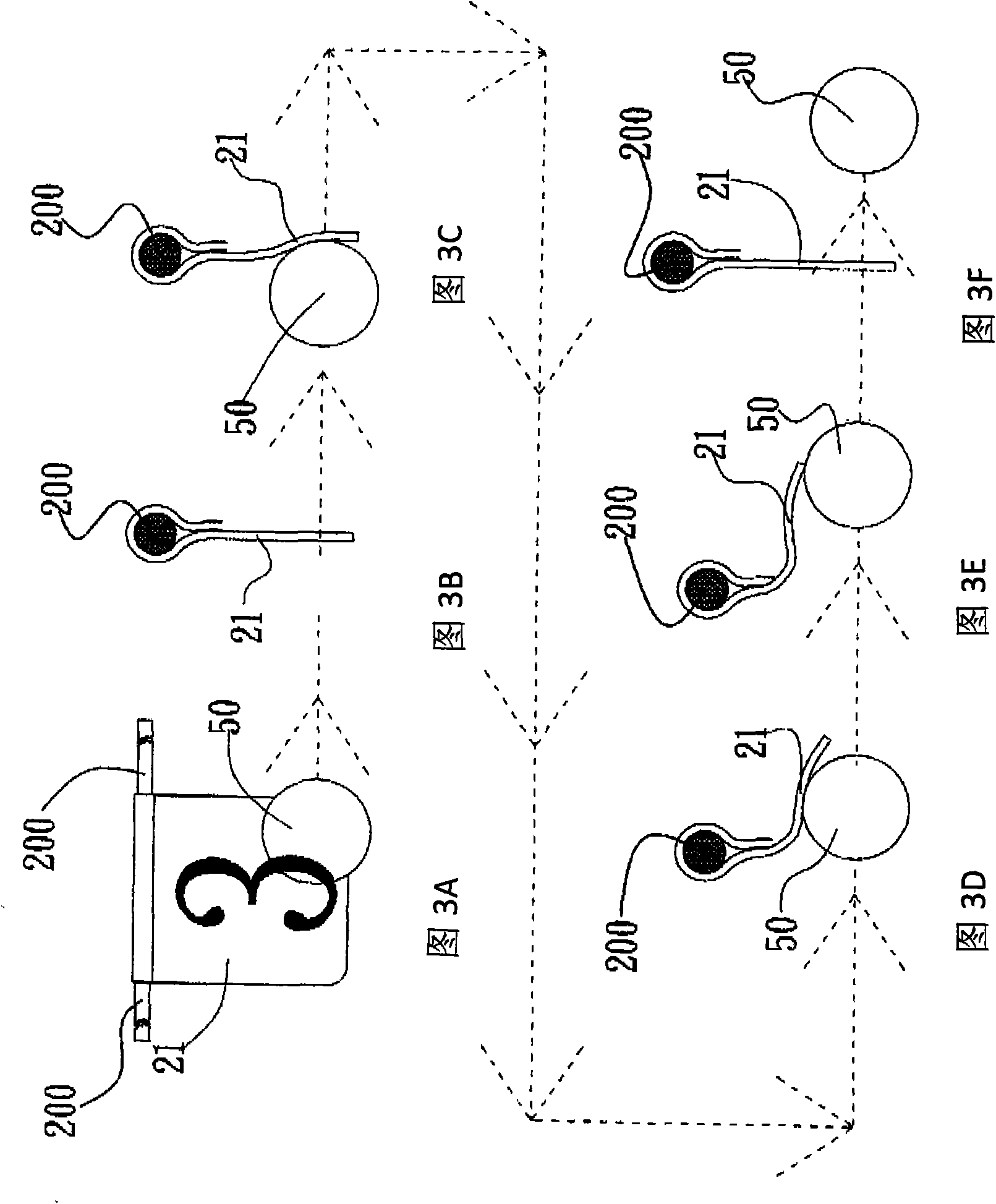
[0079] See figure 1 as shown, figure 1 It is a three-dimensional schematic diagram of the external front of the target body of the present invention Figure 1 . The structure of the target body 10 applicable to the sphere of the present invention is provided with a strip 200, and an obvious target surface 21 is vertically arranged on the strip 200 to form a target area device 20. After the target area device 20 The ball collection device 15 is arranged at the end, and the ball collection device 15 can be made of a grid-shaped buffer body 151, which can not only buffer the imp...


PUM


Abstract

The invention provides a target surface structure of a ball target body scored by a microcomputer. The target surface structure comprises at least one strip arranged on the target body, and at least one objective target surface is vertically arranged in the proper position on the strip to form an objective target area device. When the objective target surface is stricken or pushed by a ball, the objective target surface can bend and deform along the ball striking way; after the ball passes through the objective target surface, the objective target surface quickly restores to the original shape; and the objective target surface not only can bear many times of striking and bending but also has a function of buffering the impact force of the ball. A coordinate position infrared sensor is arranged in the proper position of the objective target area device. When the ball is launched to fly through the coordinate position infrared sensor, the coordinate position infrared sensor in the coordinate position can be triggered, and the generated sensing coordinate signal can be transferred to the CPU of the microcomputer of an electronic displaying and scoring device for computational discrimination to obtain an electronic function of automatic scoring of ball games through voice, sound and light.

Description


Claims


Application Information

Patent Timeline
Owner 卓钰富
Features
  • Generate Ideas
  • Intellectual Property
  • Life Sciences
  • Materials
  • Tech Scout
  • Unparalleled Data Quality
  • Higher Quality Content
  • 60% Fewer Hallucinations
Learn More