
Apparatus and method for making a forming structure

a technology of forming structure and apparatus, applied in the field of forming structure, can solve the problems of reducing fluid retention, affecting the smoothness of the surface aberration of the web, and affecting the smoothness of the surface aberration,

Inactive Publication Date: 2007-12-04
PROCTER & GAMBLE CO
View PDF75 Cites 31 Cited by
  • Summary
  • Abstract
  • Description
  • Claims
  • Application Information

AI Technical Summary

Benefits of technology

"The patent describes a method for making a forming structure with columnar protrusions extending from it. The method involves using a forming unit, a backing film, a foraminous element, and a liquid photosensitive resin. The resin is applied to the foraminous element and then exposed to light through a mask to partially cure it. The resulting structure has monolithic slabs with protrusions that are joined to it. The method can also include laser etching to form apertures in the structure. The technical effect of this method is the ability to make a forming structure with columnar protrusions that have a unique structure and can be used for various applications."

Problems solved by technology

Despite its advancements in eliminating gloss, the structure of the surface aberrations of the web in Ahr, et al. can lack desired softness.
This lack of sufficient deflection detracts from the softness impression experienced by the user's skin.
These pathways in the web structures therefore cause decreased fluid retention and increased rewet in the absorbent structures.
The compression resistance of the rigid polymers helps reduce rewet, but the rigid polymers utilized tend to decrease the softness of the web.
Due to the many interstices of the microapertures that can retain water, drying commercial quantities of these webs consumes significant amounts of energy, and can require significant capital investments in drying equipment.
One further drawback associated with the webs disclosed in Curro '643 and Lee '462 when used as topsheets on sanitary napkins is the tendency of the microapertures to entrap fluid, such as menses.
This contact negatively affects the skin health of the wearer and causes the topsheet to not have a clean appearance post-use.
However, screen printing is a relatively slow process for making commercial webs for consumer articles.

Method used


Image

  • Apparatus and method for making a forming structure
  • Apparatus and method for making a forming structure
  • Apparatus and method for making a forming structure

Examples


Embodiment Construction

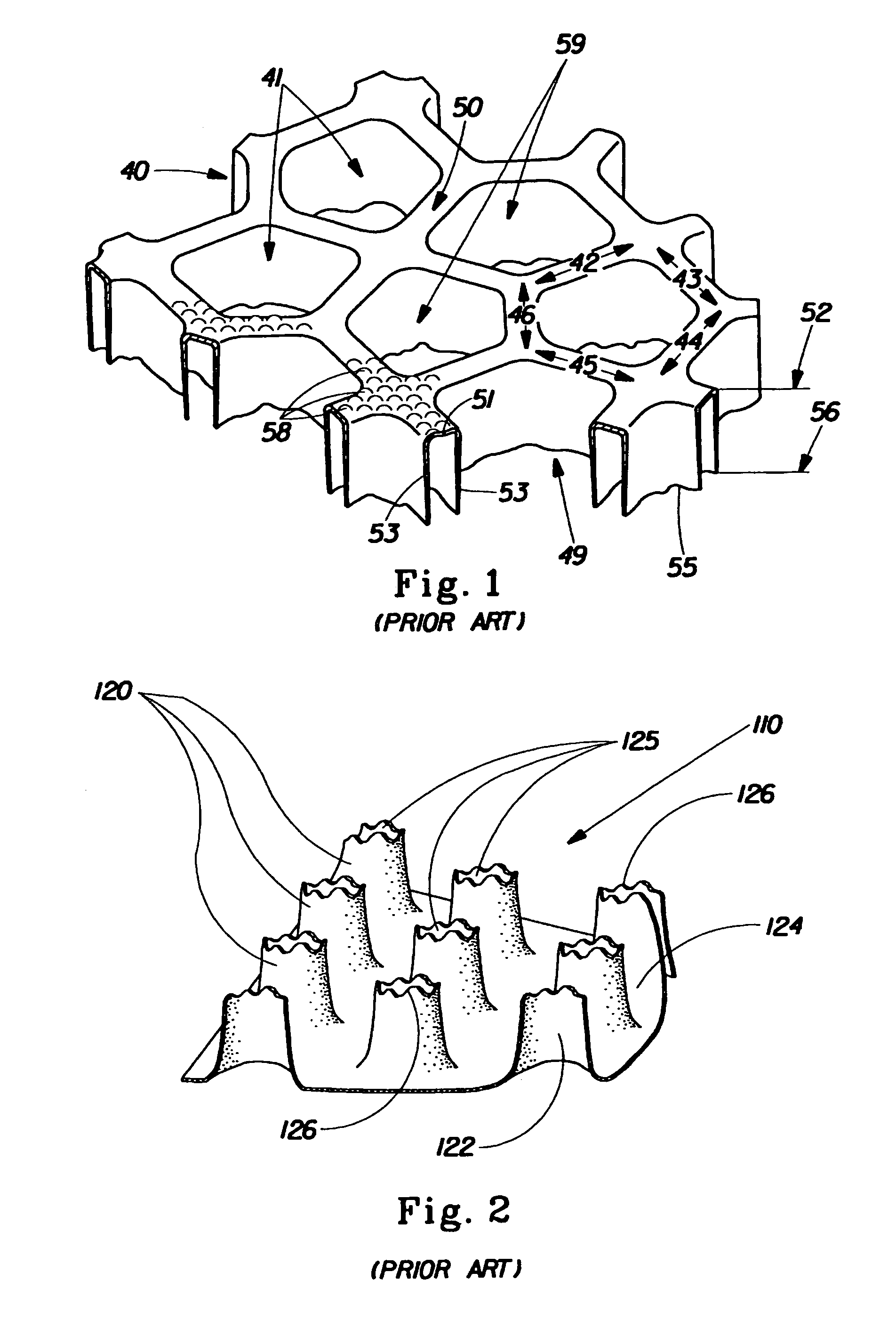
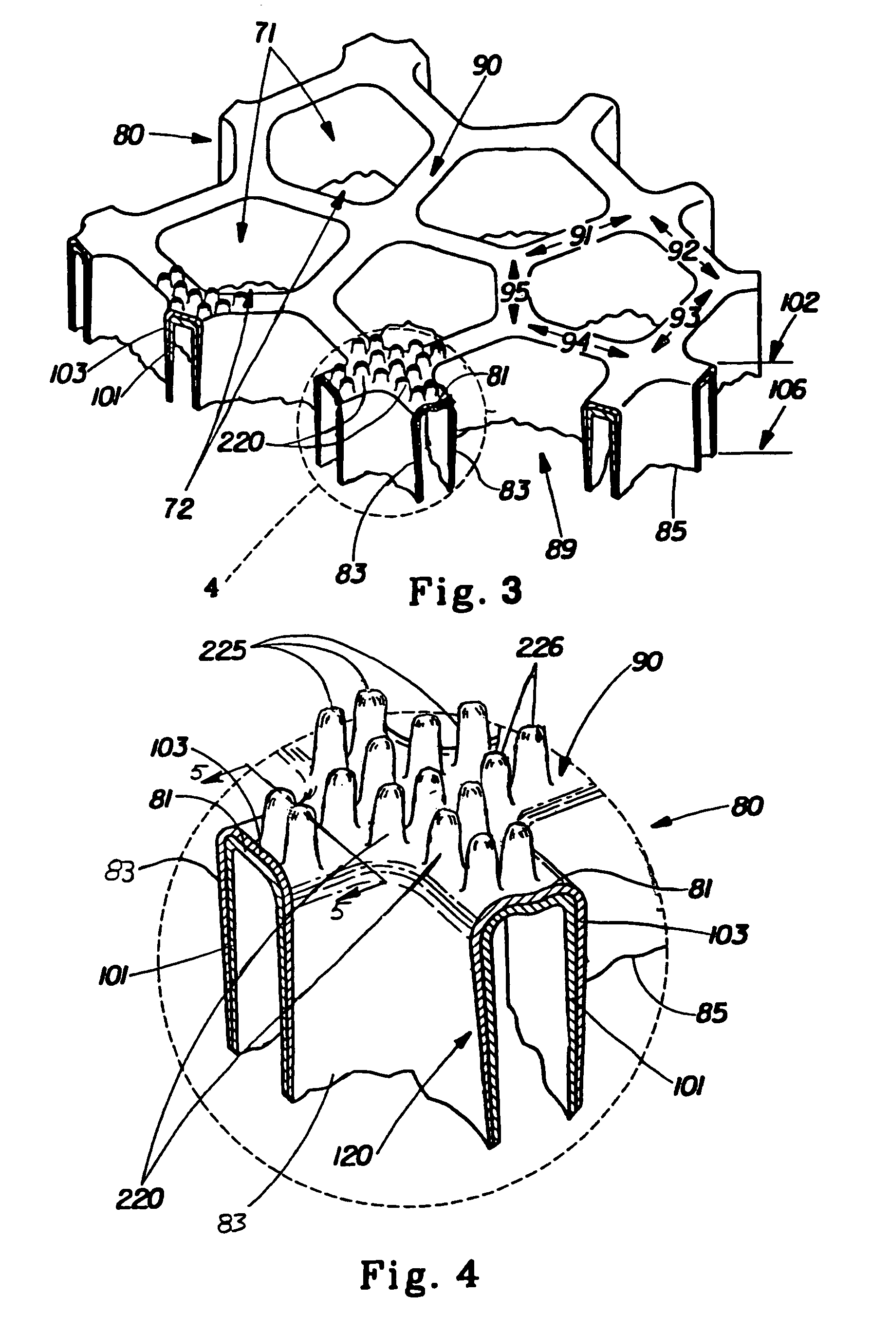
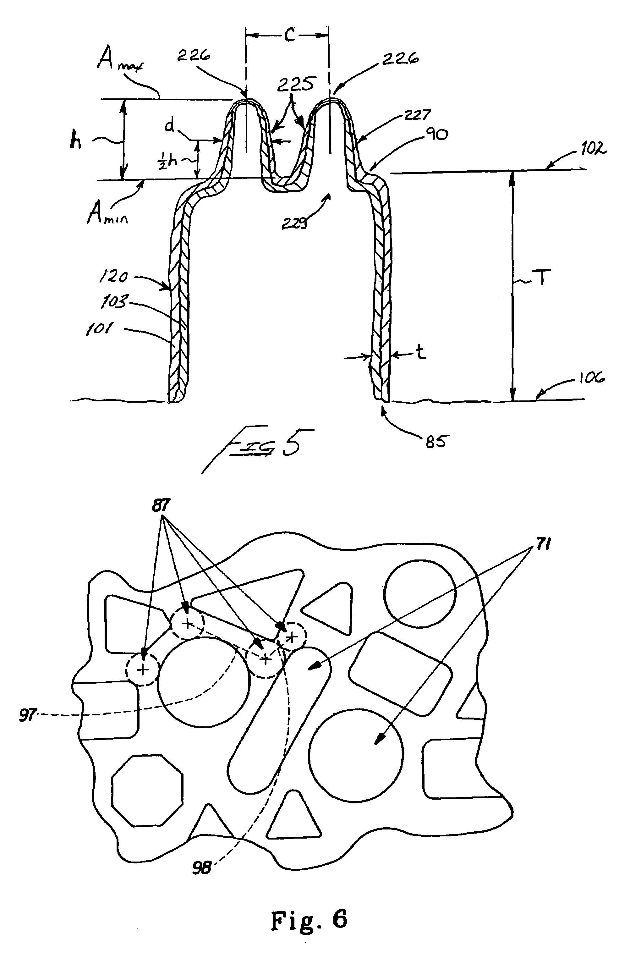
[0062]FIG. 1 is an enlarged, partially segmented perspective illustration of a prior art macroscopically-expanded, three-dimensional, fluid pervious polymeric web 40 formed generally in accordance with the aforementioned U.S. Pat. No. 4,342,314. Webs of this type have been found to be highly suitable for use as a topsheet in absorbent articles such as sanitary napkins, pantyliners, interlabial devices, and the like. The fluid pervious web 40 exhibits a plurality of macroscopic surface aberrations that can be apertures, such as primary apertures 41. Primary apertures 41 are formed by a multiplicity of interconnecting members, such as fiber like elements, e.g., 42, 43, 44, 45 and 46, that are interconnected to one another to define a continuous first surface 50 of the web 40. Each fiber like element has a base portion, e.g., base portion 51, located in plane 52 of first surface 50. Each base portion has a sidewall portion, e.g., sidewall portion 53, attached to each longitudinal edge ...


PUM


Abstract

A method for making a forming structure having columnar protrusions extending therefrom comprising the steps of exposing a liquid photosensitive resin to light having an activating wavelength thereby inducing partial curing of the photosensitive resin to form a monolithic slab of partially-cured photosensitive resin; and, including the step of inducing partial curing of a plurality of protrusions on the monolithic slab such that they are joined to and integral with the monolithic slab. The method can further comprise the step of laser etching a plurality of apertures through the forming structure.

Description

CROSS REFERENCE TO RELATED APPLICATION[0001]This application is a continuation-in-part of pending U.S. Ser. No. 10 / 324,181, filed on Dec. 20, 2002.FIELD OF THE INVENTION[0002]The present invention relates to a forming structure for making a polymeric web exhibiting a soft and silky tactile impression on at least one surface. More particularly, the present invention relates forming structure for making a three-dimensional polymeric web exhibiting a soft and silky tactile impression that can be used as a body-facing topsheet in disposable absorbent.BACKGROUND OF THE INVENTION[0003]It is extremely desirable to construct disposable articles, such as absorptive devices, including sanitary napkins, pantyliners, interlabial devices, diapers, training pants, incontinent devices, wound dressings and the like, with a soft cloth-like surface feel to the user's skin at any anticipated points of contact. Likewise, it has long been known in the disposable articles art to construct absorptive devi...

Claims


Application Information

Patent Timeline
Patent Type & Authority Patents(United States)
IPC IPC(8): G03F7/26A61F13/15B23K26/00B23K26/06B23K26/36B23K26/38B26F1/26B29C59/02B29C59/06B29C59/16D04H1/46D06C23/00
CPCA61F13/15731B23K26/0024B23K26/0036B23K26/0048B23K26/06B23K26/365B23K26/381B26F1/26B29C59/025B29C59/06B29C59/16G03F7/0015B23K26/383B23K26/4065A61F13/512Y10T428/24273B29C2791/009B29L2031/4878Y10T428/24174B23K26/0006B23K26/382B23K26/384A61F13/51121A61F13/5122B23K26/361B23K2103/16B23K2103/30B23K2103/42B23K2103/50Y10T428/31504B33Y80/00A61F13/15B26F1/00B23K26/02B29C59/00G03F7/26
Inventor GRAY, BRIAN FRANCISSTONE, KEITH JOSEPHGROSS, SARAH BETHO'NEIL, JULIE ANNFIEDELDEY, TIMOTHY PAUL
Owner PROCTER & GAMBLE CO
Learn More