Supercharge Your Innovation With Domain-Expert AI Agents!

Variable length encoding method and variable length decoding method

a variable length and encoding technology, applied in the field of variable length encoding method and variable length decoding method, can solve the problems of reducing coding efficiency and causing the same problem, and achieve the effect of improving coding efficiency

Active Publication Date: 2007-12-04
GK BRIDGE 1
View PDF23 Cites 37 Cited by
  • Summary
  • Abstract
  • Description
  • Claims
  • Application Information

AI Technical Summary

Benefits of technology

This approach significantly improves coding efficiency by adapting code lengths to coefficient values, reducing the overall code length and processing time, especially for large coefficients, while maintaining efficient decoding.

Problems solved by technology

However, using the existing method engenders a decrease in coding efficiency since the code length gets longer as the number of consecutive zero coefficients R and a coefficient value L get larger.
Even when coding L separately from R (one-dimensional coding of L) using a single VLC table, the same problem occurs as in the case of coding R and L as a pair.

Method used


Image

  • Variable length encoding method and variable length decoding method
  • Variable length encoding method and variable length decoding method
  • Variable length encoding method and variable length decoding method

Examples


first embodiment

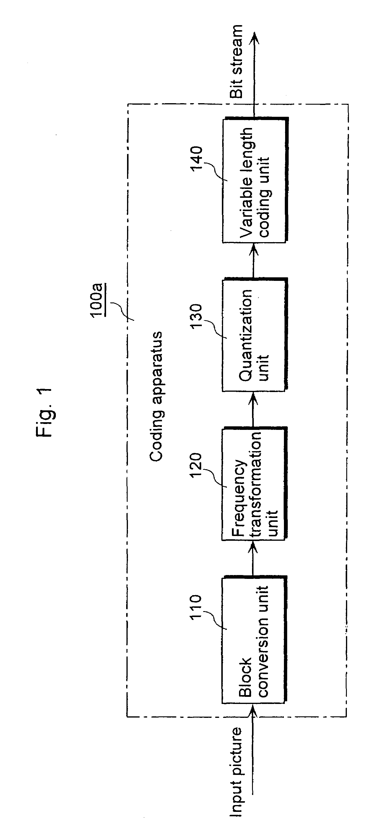
[0064]FIG. 1 is a block diagram showing a functional structure of a coding apparatus to which the moving picture coding method according to the present invention is applied. The first embodiment illustrates the functional structure in a case of intra-picture coding an input picture using the moving picture coding method according to the present invention.

[0065]As shown in the diagram, a coding apparatus 100a is comprised of a block conversion unit 110, a frequency transformation unit 120, a quantization unit 130 and a variable length coding unit 140. Each unit composing such coding apparatus 100a is realized with a CPU, a ROM for storing in advance a program or data executed by the CPU and a memory for providing a work area when the program is executed as well as for storing temporally the input picture, or the like.

[0066]The block conversion unit 110 divides the input picture into blocks, each of which is sized 4 (horizontal)×4 (vertical) pixels and outputs each pixel block to the ...

second embodiment

[0101]FIG. 8 is a block diagram showing a functional structure of a decoding apparatus to which the variable length decoding method according to the embodiments of the present invention is applied. Here, the bit stream generated using the variable length coding method according to the present invention described in the first embodiment shall be inputted.

[0102]As shown in FIG. 8, a decoding apparatus 500a is comprised of a variable length decoding unit 510, an inverse quantization unit 520, an inverse frequency transformation unit 530 and a picture memory 540. Each unit composing such decoding apparatus 500a, like the coding apparatus 100a, is realized with a CPU, a ROM for storing in advance a program or data executed by the CPU and a memory for providing a work area when the program is executed as well as for storing temporally the input picture, or the like.

[0103]The bit stream is inputted to the variable length decoding unit 510. The variable length decoding unit 510 decodes the ...

third embodiment

[0131]The following describes a coding apparatus according to the third embodiment with reference to the diagrams.

[0132]FIG. 13 is a block diagram showing a structure of the coding apparatus 100b according to the third embodiment of the present invention.

[0133]This picture coding apparatus 100b, which performs intra-picture coding on an input picture (picture data) with improved coding efficiency, is comprised of a block conversion unit 101, a frequency transformation unit 102, a quantization unit 103, and a variable length coding unit 150.

[0134]The block conversion unit 101 divides the input picture into pixel blocks, each of which has a size of 4 (horizontal)×4 (vertical) pixels, and outputs them to the frequency transformation unit 102.

[0135]The frequency transformation unit 102 performs frequency transformation on each of the divided pixel blocks so as to generate frequency coefficients. Then, the frequency transformation unit 102 outputs the generated frequency coefficients to ...


PUM


Abstract

A variable length coding method is provided for coding coefficients in each block which are obtained by performing frequency transformation on picture data of a moving picture per block having a predetermined size, and includes: a coefficient scanning step of scanning the coefficients in the block in a predetermined order; and a coding step of coding the coefficients scanned in the coefficient scanning step into variable length codes in a predetermined order by switching a plurality of tables to be used for coding. Here, a direction of switching between the tables may be one-directional. Also, the coding may be non-arithmetic coding.

Description

TECHNICAL FIELD[0001]The present invention relates to a variable length coding method for coding coefficients in each block which are obtained by performing frequency transformation on picture data of a moving picture per block having a predetermined size, as well as a variable length decoding method, and the like.BACKGROUND ART[0002]In coding a moving picture, compression of information volume is usually performed by utilizing redundancies both in spatial and temporal directions which the moving picture has. Usually, a transformation into a frequency domain is used as a method of utilizing the spatial redundancy while inter picture prediction coding is used as a method of utilizing the temporal redundancy.[0003]In a moving picture coding method which is presently under the process of standardization, quantization is performed on each block sized 4×4 pixels so as to generate coefficients after frequency transformation is performed on such block, with the view to enhance coding effic...

Claims


Application Information

Patent Timeline
Patent Type & Authority Patents(United States)
IPC IPC(8): H04B1/66H03M7/40H04N19/136H04N19/13H04N19/176H04N19/189H04N19/196H04N19/423H04N19/60H04N19/91
CPCH03M7/40H04N19/14H04N19/134H04N19/18H04N19/61H04N19/60H03M7/4006H04N19/93H04N19/13H04N19/136H04N19/44H04N19/91H04N19/122H04N19/124H04N19/172H04N19/182H04L47/29H04N19/176
Inventor KONDO, SATOSHIKADONO, SHINYAHAGAI, MAKOTOABE, KIYOFUMI
Owner GK BRIDGE 1
Features
  • R&D
  • Intellectual Property
  • Life Sciences
  • Materials
  • Tech Scout
  • Unparalleled Data Quality
  • Higher Quality Content
  • 60% Fewer Hallucinations
Learn More