Slot device

a slot device and slot technology, applied in the direction of coupling device connection, electrical apparatus casing/cabinet/drawer, instruments, etc., can solve the problems of difficulty in insertion, size, thickness, and increase of the slot device, so as to achieve the effect of increasing the height of the slot device and not increasing the slot heigh

Active Publication Date: 2007-12-11
LENOVO PC INT
View PDF17 Cites 18 Cited by
  • Summary
  • Abstract
  • Description
  • Claims
  • Application Information

AI Technical Summary

Benefits of technology

[0013]The present invention thus provides a slot device that enables the efficient insertion, into a slot, of a card type insertion / ejection member such that the front of the card, in the insertion direction, need not be formed thinner than the succeeding portion, and for which the height of the slot need not be increased. Described herein is a slot device that is capable of receiving both a 34 mm ExpressCard and a 54 mm ExpressCard, wherein the slot device includes oblique guides that laterally direct the 34 mm ExpressCard and the 54 mm ExpressCard to appropriate male connectors in the slot device. The slot device affords a smooth insertion of both the 34 mm ExpressCard and the 54 mm ExpressCard without a height of the slot device being increased. The slot device further includes: a lower chassis ceiling wall that defines a lower face side of a card storage space; and a slot side edge that is formed from a rear-side inclined portion and a slot-side include portion, wherein the rear-side inclined portion and the slot-side inclined portion are respectively inclined at angles σ1 and σ2, wherein angles σ1 and σ2 are relative to a reference cross section of the slot device, and wherein σ1<σ2 to optimize guidance of the 34 mm ExpressCard and the 54 mm ExpressCard towards their respective male pins in the slot device.

Problems solved by technology

On the other hand, in the ExpressCard slot device used for ExpressCards having 54 and 34 mm widths, since the guide wide walls are formed to accept an ExpressCard having a width of 54 mm, it is difficult for a narrow ExpressCard having a width of 34 mm to be moved to the rear of the storage space, while the horizontal posture is maintained along the right and left guide walls.
Therefore, when an ExpressCard is inserted into the slot, the ExpressCard contacts the upper and lower walls of the slot, and insertion is not easy.
In this case, accordingly, the size, the thickness, of the slot device is also increased, and for the downsizing of the slot device, this means is very disadvantageous.
According to the PC card slot device described in Japanese Patent Laid-Open Publication No. 2000-182712, since the movable tray that interlocks with the push rod of the ejection mechanism is provided, the structure is complicated.

Method used


Image

  • Slot device
  • Slot device
  • Slot device

Examples


Embodiment Construction

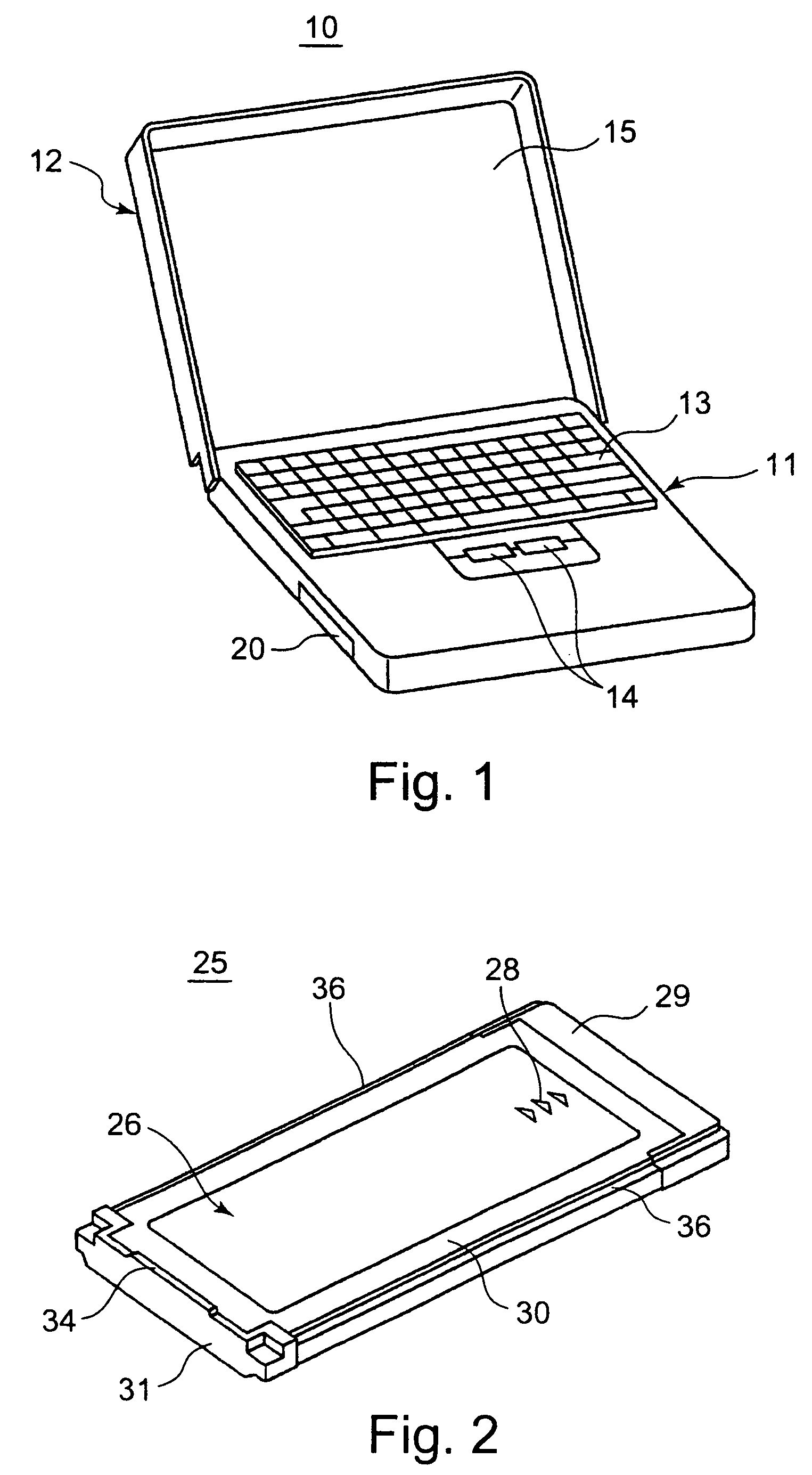
[0028]Reference is now made to the figures, and particularly to FIG. 1, which is a perspective view of a notebook PC 10. The notebook PC 10 includes: a PC main body 11; and a cover 12, the lower end of which is rotatably attached to the rear side of the PC main body 11 so as to expose and cover the upper face of the PC main body 11. A keyboard 13 and a clicking key 14 are provided on the upper face of the PC main body 11, and the clicking key 14 is positioned in front of the keyboard 13. A color liquid crystal display device 15 is mounted on the inner face of the cover 12. A PC (personal computer) slot device 20 is mounted in the PC main body 11 so that an ExpressCard or a PC card can be inserted into or extracted from the side of the PC main body 11. The PC slot device 20 has a door that is closed to hide the internal slot when a card, such as an ExpressCard, has not been inserted into the PC slot device 20. When the front end of a card, such as an ExpressCard, abuts upon the door,...


PUM


Abstract

A PC card slot device for an ExpressCard affords a smooth insertion of the ExpressCard into a slot for the PC card slot device, without the height of the slot being increased. A lower chassis ceiling wall defines the lower face side of a card storage space, and also includes a slot side edge that is formed of a rear-side inclined line portion and a slot-side inclined line portion. The rear-side inclined line portion and the slot-side inclined line portion are respectively inclined at angles α1 and α2, relative to a reference cross section. To insert the ExpressCard into the slot of the card storage space, the right corner of the right upper level lower face portion of the card is inserted into the card storage space and the front end of the right stepped portion of the card is guided along the inclined line portions.

Description

PRIORITY CLAIM[0001]This application claims priority of Japanese Patent Application No. 2005-2102, filed on Jan. 7, 2005, and entitled, “Slot Device.”BACKGROUND OF THE INVENTION[0002]1. Technical Field[0003]The present invention relates to a slot device, such as an ExpressCard slot device, mounted in a notebook computer, and particularly relates to a slot device that facilitates the smooth insertion of a card type inversion / ejection member into a slot.[0004]2. Description of the Related Art[0005]Currently, typical notebook computers are equipped with PC card slot devices. The specifications for PC cards are standardized by the PCMCIA (Personal Computer Memory Card International Association), and PC cards are employed as extension devices for personal computers (hereinafter referred to as “PCs”; note, however, that the term “PC card” is itself a proper noun, and does not correspond to the term “personal computer card”). In Japanese Patent Laid-Open Publication No. 2000-182712, while ...

Claims


Application Information

Patent Timeline
Patent Type & Authority Patents(United States)
IPC IPC(8): H01R12/00
CPCG06F1/1632H05K5/0286H05K5/0265G06K7/0043
Inventor MORINO, TAKAYUKINOGUCHI, HIROYUKI
Owner LENOVO PC INT
Why Eureka
Try Eureka