Loading mechanism for infusion pump

a technology of infusion pump and loading mechanism, which is applied in the direction of catheters, needles, tube connectors, etc., can solve the problems of cumbersome loading of prior art infusion pumps

Inactive Publication Date: 2007-12-11
EUGLY DIABETES CARE LLC
View PDF42 Cites 172 Cited by
  • Summary
  • Abstract
  • Description
  • Claims
  • Application Information

AI Technical Summary

Benefits of technology

[0008]In a further embodiment of the invention, a variable volume reservoir is provided together with a plunger connected to the bottom of the reservoir. A threaded plunger rod is also provided that is connected to the plunger, such that the plunger rod is parallel to and offset from the longitudinal axis of the reservoir. The plunger rod is capable of mating with a threaded drive screw whose axis is offset from and parallel to the longitudinal axis of the reservoir. The plunger rod, when axially displaced, causes a change in volume of the reservoir. This embodiment of the invention can be used in combination with a drive assembly to deliver a fluid.

Problems solved by technology

Prior art infusion pumps have been cumbersome to load, requiring a series of steps that often require the user to carefully align components of a pump drive assembly with the syringe.

Method used


Image

  • Loading mechanism for infusion pump
  • Loading mechanism for infusion pump
  • Loading mechanism for infusion pump

Examples


Embodiment Construction

[0018]Embodiments of the present invention advantageously address simplifying the loading of medication reservoirs in an infusion pump.

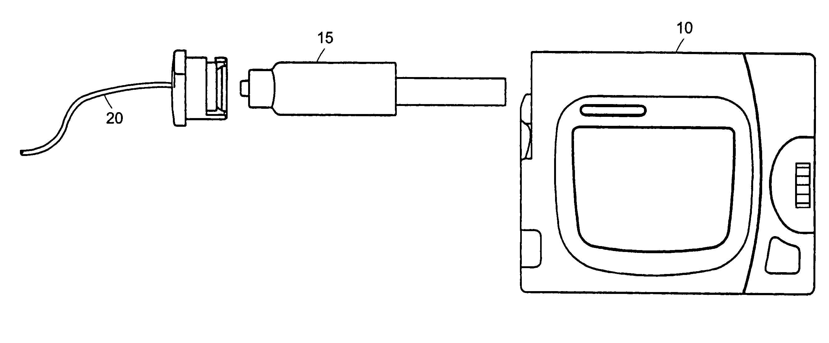
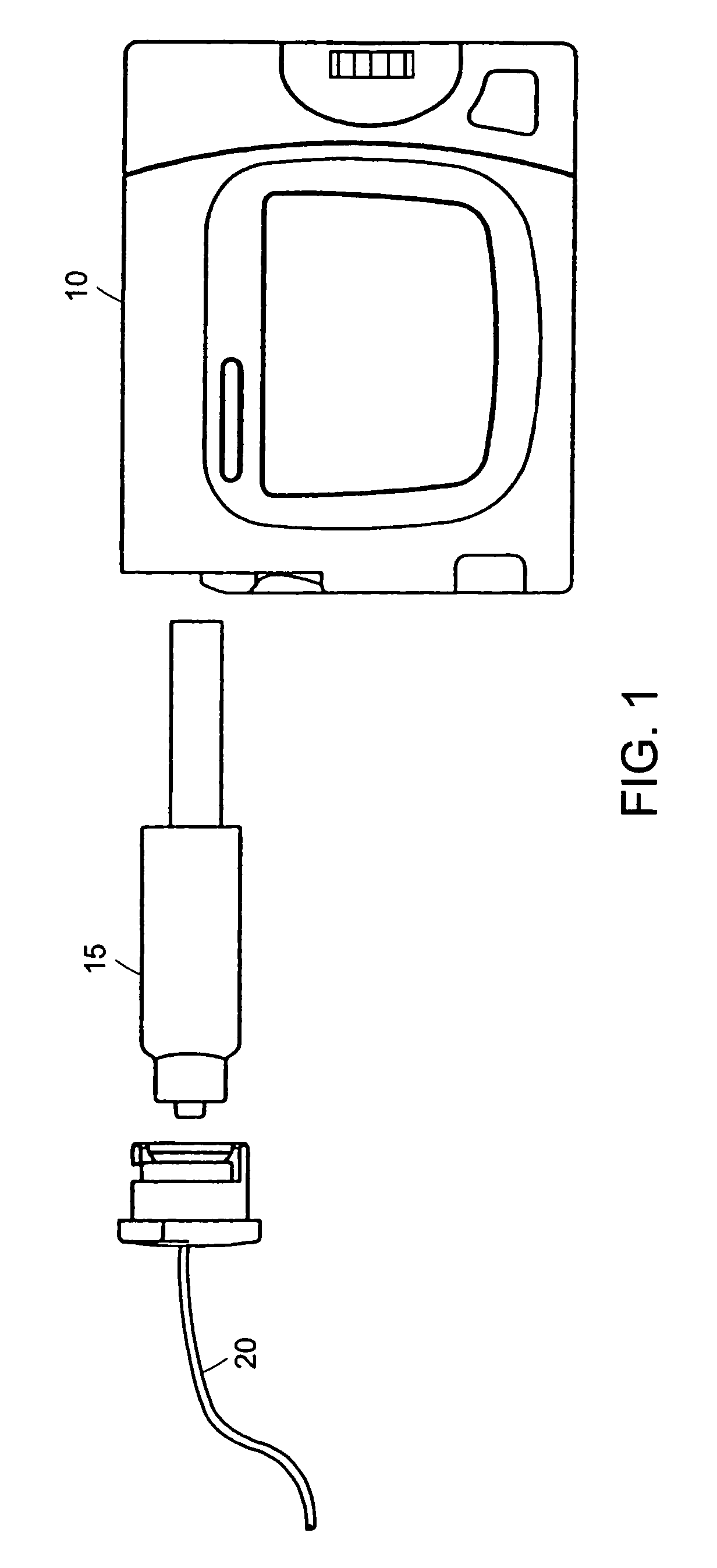
[0019]FIG. 1 is an overall view of an infusion pump according to an embodiment of the present invention. A pump assembly 10 contains the components needed to cause a reservoir assembly 15 to deliver medication to a user. The reservoir assembly 15 may contain enough medication, such as insulin, for several days for a typical user. A tubing set 20, connected to the reservoir assembly, contains the cannula through which the medication is delivered to the user.

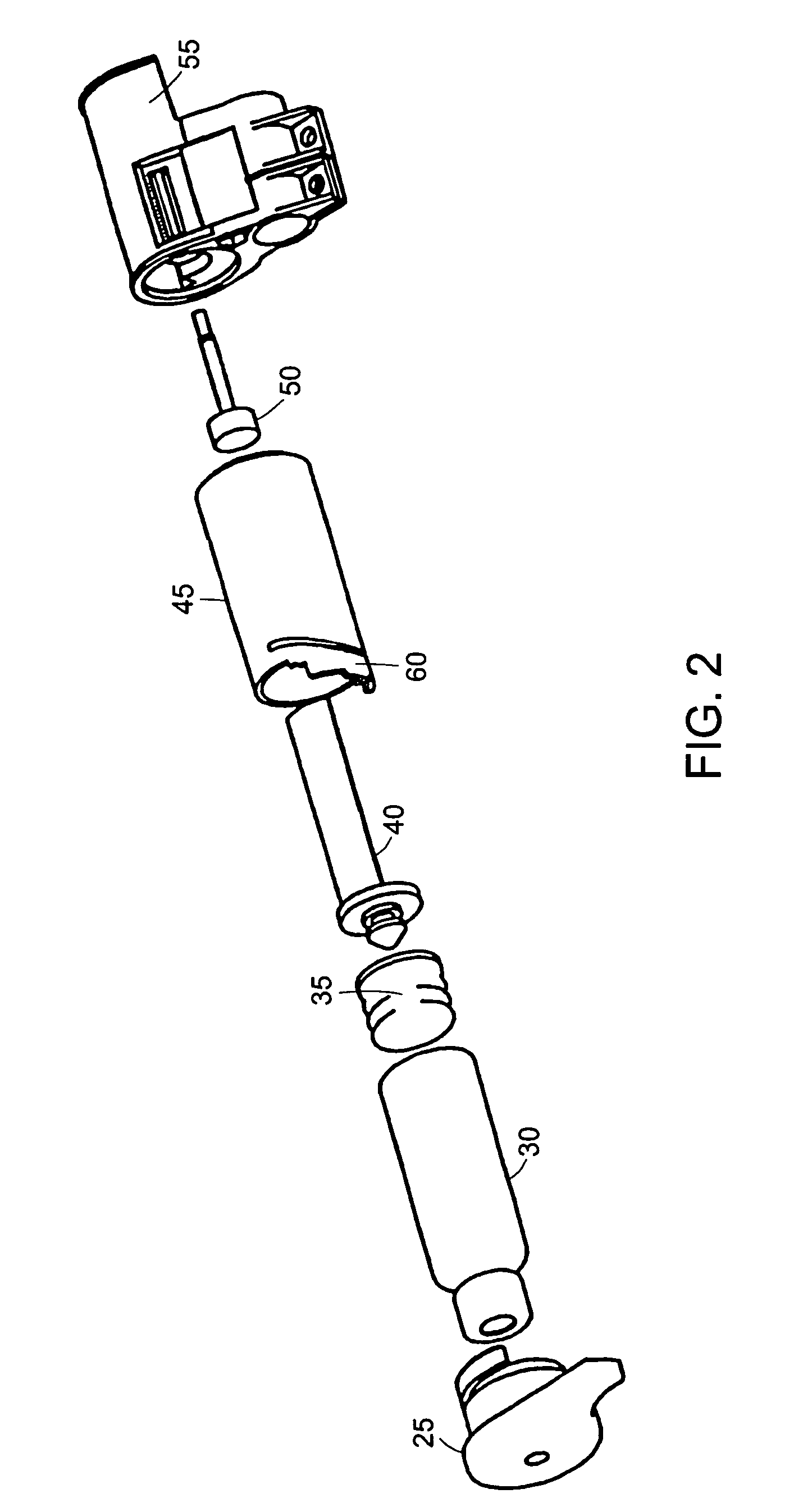
[0020]FIG. 2 shows an exploded view of the drive mechanism of the infusion pump. A reservoir assembly 15 comprises a reservoir 30, plunger 35 and plunger rod 40. The reservoir 30 contains the medication for delivery to the user and is of variable interior volume. The interior volume is the liquid capacity of the reservoir. The plunger 35, inserted into the bottom of the reservoir, causes the volume...


PUM


Abstract

A loading mechanism for a medication infusion pump. The mechanism includes a medication reservoir, a plunger, a threaded plunger rod offset from the axis of the reservoir and an infusion pump with a drive screw that is offset from the axis of a pump barrel. The pump barrel receives the assembly comprising the reservoir, plunger and plunger rod.

Description

TECHNICAL FIELD AND BACKGROUND ART[0001]The present invention relates to medical infusion pumps and more particularly to improved devices for loading medication reservoirs.[0002]Medical infusion pumps have been advantageously employed, for example, to simulate the action of the human pancreas, providing a continuous delivery of insulin to patients with diabetes. These pumps typically include a microprocessor controlled syringe pump, an insulin filled syringe, a hub and tubing set and a cannula. The pump is often worn in a carrying case on the patient's belt or in other locations such as a pocket. The syringe is mounted in the syringe pump and can contain enough insulin for several days. The hub connects the syringe to the tubing set. The cannula is at the end of the tubing set and can be either steel or softer teflon. The cannula is inserted into fatty tissue and the insulin is injected subcutaneously.[0003]Prior art infusion pumps have been cumbersome to load, requiring a series of...

Claims


Application Information

Patent Timeline
Patent Type & Authority Patents(United States)
IPC IPC(8): A61M1/00A61M1/36A61M5/14A61M5/142A61M5/145A61M5/158A61M25/06A61M39/10A61M39/14
CPCA61M5/1456A61M5/158A61M5/14A61M5/142A61M5/1452A61M5/14546A61M2005/1587A61M25/0612A61M39/1011A61M39/14A61M2005/14573A61M2005/1581
Inventor GRAY, LARRY B.LANIGAN, RICHARD
Owner EUGLY DIABETES CARE LLC
Why Eureka
Try Eureka