Electrical box assembly with internal mounting arrangement and flange to seal against air infiltration

a box assembly and mounting arrangement technology, applied in the field of electric boxes, can solve the problems of reducing the usable affecting the service life of the box, and the inability to fit a large electrical component, the receptacle, and the resulting box, so as to reduce the volume of the box, eliminate the large internal volume, and facilitate the sealing around the cable opening.

Active Publication Date: 2007-12-11
ARLINGTON INDS
View PDF20 Cites 23 Cited by
  • Summary
  • Abstract
  • Description
  • Claims
  • Application Information

AI Technical Summary

Benefits of technology

[0009]A first advantage of the electrical box assembly of the present invention is that it provides an airtight electrical box installation. The electrical box assembly includes a transversely extending flange to seal around the outer periphery of the box. Adjustable knockouts in the sidewalls include multiple removable sections, which can be removed selectively as desired to create large or small openings for electrical cables and thereby minimize open areas and enable easier sealing around the cable openings.
[0010]Another advantage provided by the electrical box assembly of the present invention is that the mounting arrangement is integral with a separate insert portion of the electrical box rather than with the box itself. As a result, the fastener receptacles formed integral with the insert do not take up a great amount of usable volume within the box, as is the case with prior art boxes in which fastener receptacles are formed integral with the box. Prior art boxes are typically molded in one piece, with the fastener receptacles internal to the box. Molding a box in one piece eliminates a large amount of internal volume and makes it impossible to fit a large electrical component, such as a ground fault receptacle, within the resulting box. The two-piece electrical box assembly of the present invention provides a large internal volume with ample space for bulky devices such as ground fault receptacles.
[0011]A further advantage of the electrical box assembly of the present invention is that the internal mounting arrangement is located within the confines of the internal enclosure rather than behind the outward extending flange. Therefore the mounting arrangement is easily accessible by the installer and is not obscured by the flange.
[0012]Another significant advantage is that the electrical box assembly of the present invention does not include double wall construction. The box can therefore be easily molded of plastic.
[0013]These and other objects and advantages of the present invention will be better understood by reading the following description along with reference to the drawings.

Problems solved by technology

As a result, the fastener receptacles formed integral with the insert do not take up a great amount of usable volume within the box, as is the case with prior art boxes in which fastener receptacles are formed integral with the box.
Molding a box in one piece eliminates a large amount of internal volume and makes it impossible to fit a large electrical component, such as a ground fault receptacle, within the resulting box.

Method used


Image

  • Electrical box assembly with internal mounting arrangement and flange to seal against air infiltration
  • Electrical box assembly with internal mounting arrangement and flange to seal against air infiltration
  • Electrical box assembly with internal mounting arrangement and flange to seal against air infiltration

Examples


Embodiment Construction

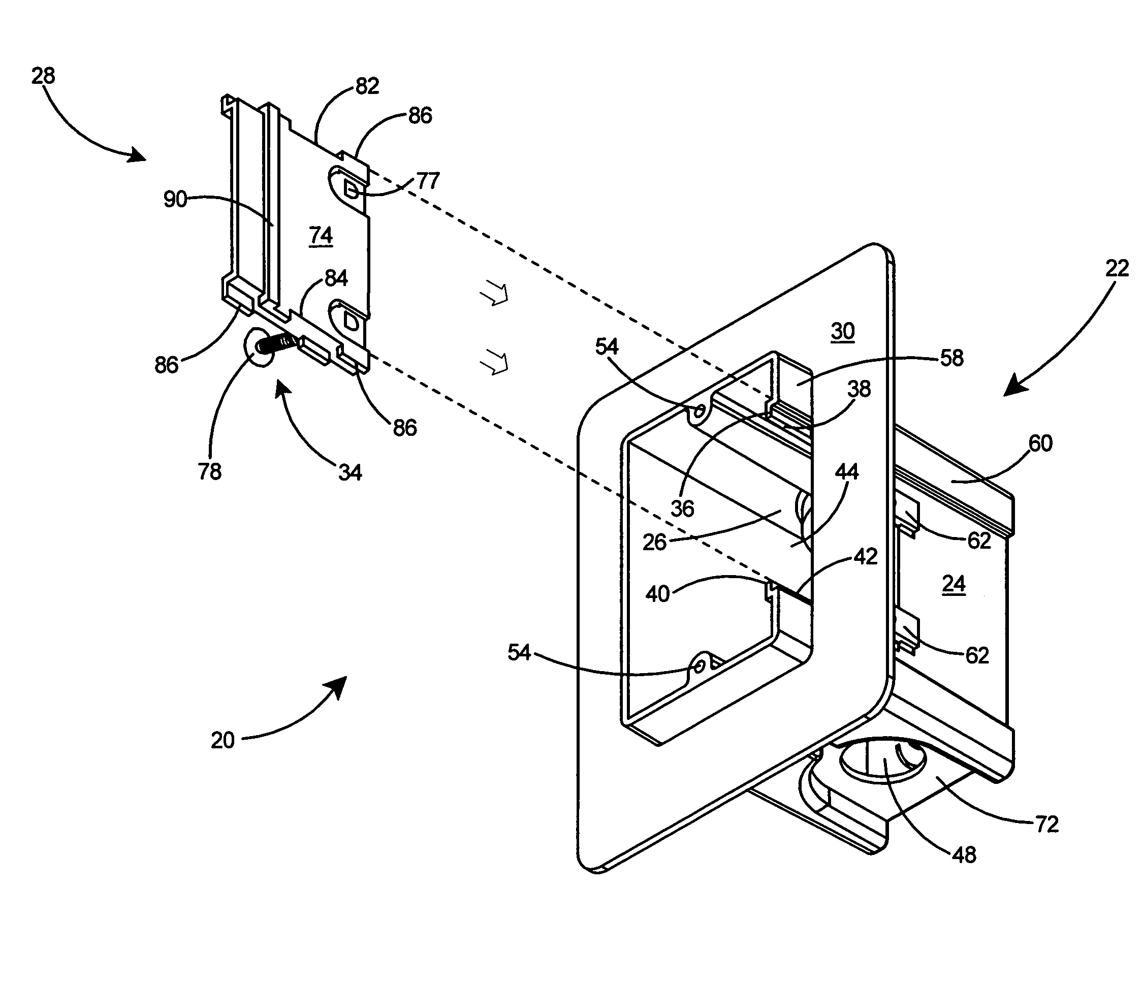
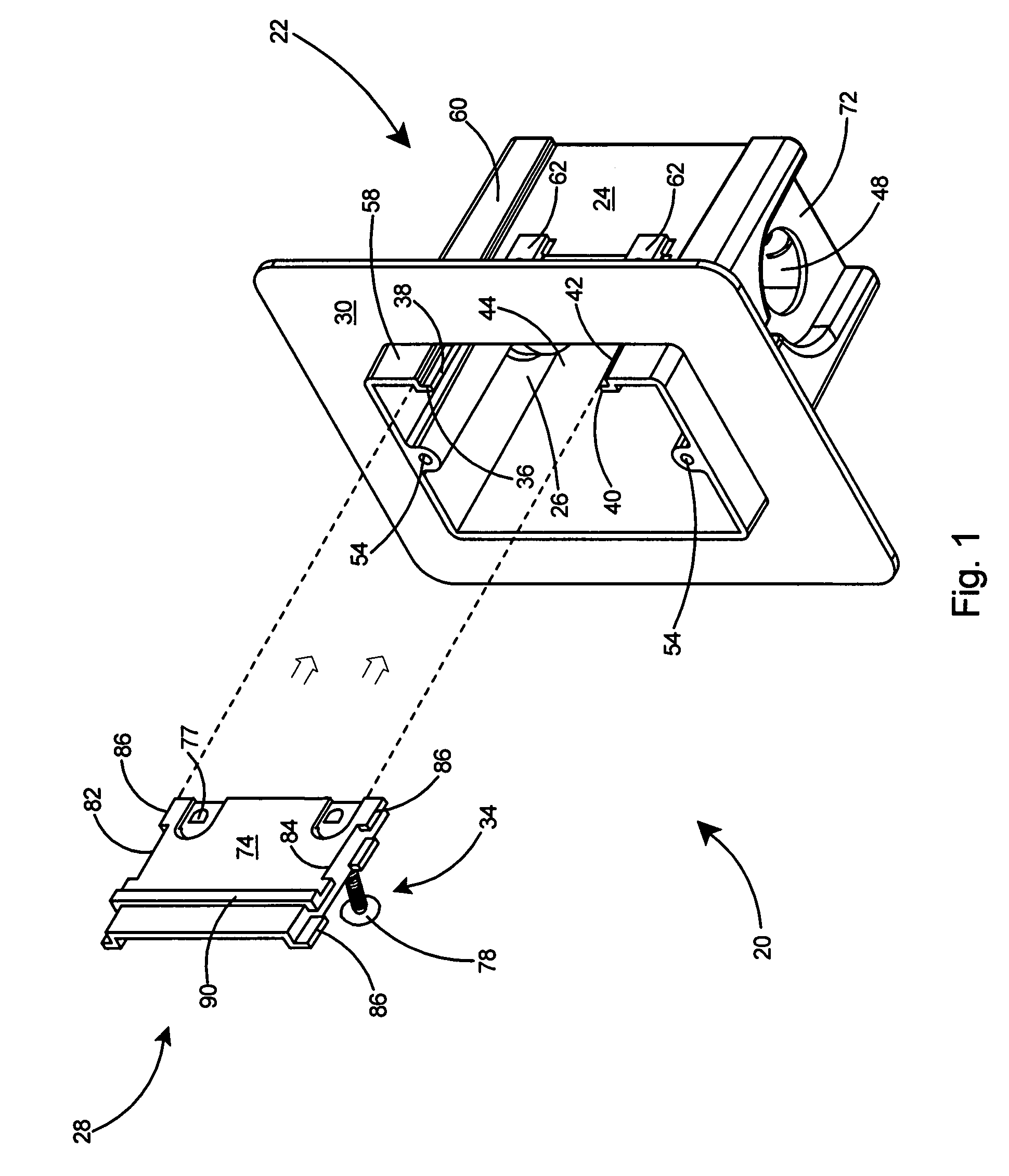
[0027]With reference to a preferred embodiment in FIG. 1, the present invention is an electrical box assembly 20 for minimizing air infiltration when mounted on an interior wall of a structure. The electrical box assembly 20 includes a box member 22 including sidewalls 24, an opening 26 in one of the sidewalls 24, and a panel 28 that can be inserted and locked within the opening 26. The electrical box assembly includes a flange 30 extending outward transversely from the outer periphery 32 of the sidewalls 24 and a mounting arrangement 34 on the panel 28 for securing the box member 22 to a stud (not shown). The box member 22 includes a first rail 36 extending along a first edge 38 of the opening and a second rail 40 extending along a second edge 42 of the opening 26. The box member 22 includes a channel 44 formed between the rails 36 and 40 in the sidewall 24.

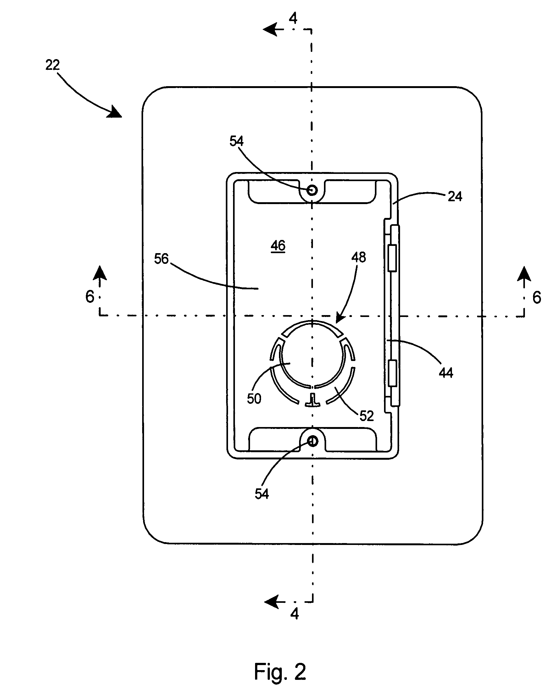
[0028]Referring to FIG. 2, the box member 22 includes a back wall 46 and a knockout area 48 in the back wall 46. The knockout ...


PUM


Abstract

An electrical box with sidewalls having a front edge and a flange extending transversely from the sidewalls at a set distance from the front edge. Knockouts in the sidewalls include multiple removable sections, which can be removed selectively as desired to create large or small openings for electrical cables. The sidewalls of the electrical box include an opening therein and a panel that can be inserted into the opening. The panel includes an internal mounting arrangement with captive fasteners for securing the electrical box to a stud. The flange provides a sealing surface for contacting the vapor barrier surrounding the box and thereby seals around the periphery of the electrical box. Duct seal is applied around the periphery of the cables at the knockout areas to provide an airtight seal for the electrical cables entering the electrical box.

Description

FIELD OF THE INVENTION[0001]This invention relates to electrical boxes and specifically to an electrical box assembly including a peripheral flange to reduce air infiltration and an internal mounting arrangement for simplifying mounting to a stud.BACKGROUND OF THE INVENTION[0002]To achieve energy efficiency, a common goal in building construction, it is necessary to insulate and minimize air infiltration through walls. Typical wall construction to minimize air infiltration includes installing insulation between the studs and installing a vapor barrier, such as polyethylene, over the studs, and applying an interior wall covering such as sheetrock over the vapor barrier.[0003]Unfortunately, the installation of conventional electrical boxes on the walls oftentimes compromises the air tightness of a building. Typically, electrical boxes are fastened to the studs and wiring pulled into the boxes prior to installation of the vapor barrier. The vapor and sheet rock are typically installed ...

Claims


Application Information

Patent Timeline
Patent Type & Authority Patents(United States)
IPC IPC(8): H01H9/02
CPCH02G3/126
Inventor GRETZ, THOMAS J.
Owner ARLINGTON INDS
Why Eureka
Try Eureka