Dampened slide for an anti-chucking wedge assembly

a wedge assembly and anti-chucking technology, applied in the field of displacement limiting systems, can solve the problems of non-parallel deflection, undesirable match-boxing, and additional vehicle noise, and achieve the effects of reducing rattling, limiting deflection, and reducing rattling further

Inactive Publication Date: 2007-12-18
NEWFREY
View PDF36 Cites 29 Cited by
  • Summary
  • Abstract
  • Description
  • Claims
  • Application Information

AI Technical Summary

Benefits of technology

[0009]A dampened slide for a wedge assembly of the present invention provides several advantages. By providing deflectable members integrally connected to a slide housing which bias upon engagement within raised channels of the wedge body, the slide is biased into contact with the raised channels to reduce rattling of the slide. By providing deflectable members capable of deflecting in at least two directions, rattling is further reduced. Tabs are extended from the deflectable members which engage with shoulders created in the slide housing to limit deflection and prevent locking of the slide in a fully extended position. Non-deflecting portions are provided with the deflectable members to assist the deflectable members to fully engage with the raised channels.

Problems solved by technology

Motion of the vehicle therefore can result in “match-boxing”, or non-parallel deflection of the support posts relative to the squared sides of the lift-gate door.
Match-boxing is undesirable for several reasons.
First, side-to-side or non-parallel motion of support posts can impart additional vehicle noise, known as “chucking” at the lift-gate latch as the vehicle travels along rough or uneven surfaces.
Second, unless a mechanism is positioned between the lift-gate door edge and the support posts of the vehicle, full structural allowance for the stiffness of the lift-gate cannot be used in the design of the support structure area.
Common designs for wedge assemblies have several problems.
First, vehicle rattling noise is produced if the slide is not maintained in continuous contact with the striker plate (or vehicle support post) throughout the travel length of the slide.
Tolerances used for common wedge assembly slides permit easy translation, but can result in rattling between the parts during vehicle travel.
Second, vehicle manufacturing tolerances can result in positions of non-contact between the slide and the striker plate (or vehicle support post).
If the slide is not maintained in contact with the vehicle support post or striker plate, rattling can occur.
Third, contaminants such as dirt which contact portions of the wedge assembly can prevent the slide from moving freely, thus resulting in increased chucking or rattling noise.

Method used


Image

  • Dampened slide for an anti-chucking wedge assembly
  • Dampened slide for an anti-chucking wedge assembly
  • Dampened slide for an anti-chucking wedge assembly

Examples


Embodiment Construction

[0025]The following description of the preferred embodiment is merely exemplary in nature and is in no way intended to limit the invention, its application, or uses.

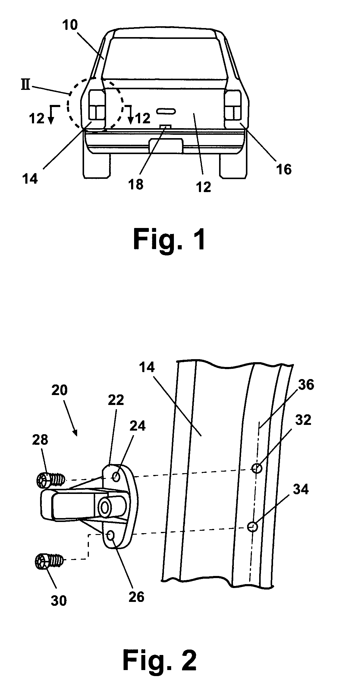
[0026]As shown in FIG. 1, a vehicle 10 includes a rear lift-gate door 12 positioned adjacent a left support post 14 and a right support post 16 of vehicle 10. A latch 18 is generally provided about mid span along a bottom edge of rear lift-gate door 12. Side edges of rear lift-gate door 12 adjacent to left support post 14 and right support post 16, respectively, are generally not latched or otherwise connectable to left support post 14 or right support post 16. For simplicity, discussion of the present invention refers in general to devices connected to left support post 14. Assemblies of the present invention are not limited to specific locations, and can be connected to right support post 16 or other component parts of vehicle 10.

[0027]As best seen in FIG. 2, a striker 20 having a striker body 22 is supported from left...


PUM


Abstract

A dampened slide for a wedge assembly includes a slide housing having perimeter walls. First and second alignment members connect to the perimeter walls, each having a deflectable portion. The deflectable portions extend opposite to each other and transverse to a centerline of the housing.

Description

CROSS-REFERENCE TO RELATED APPLICATIONS[0001]This application claims the benefit of U.S. Provisional Application No. 60 / 571,631, filed on May 14, 2004. The disclosure of the above application is incorporated herein by reference.FIELD OF THE INVENTION[0002]The present invention relates in general to displacement limiting systems and more specifically to a device and method of assembly for automobile door anti-chucking wedge assembly slides.BACKGROUND OF THE INVENTION[0003]Vehicles including automobile sport utility vehicles, station wagons, mini-vans, cross-over vehicles, cargo vans and trucks often provide an access door, commonly known as a lift-gate door. Other similar door designs include hatchback doors, sliding doors and horizontally swinging doors. Although these door designs can be mounted differently, for simplicity, these door designs will hereinafter be summarized in reference to lift-gate doors. Lift-gate doors are frequently hinged along an upper horizontal surface, and ...

Claims


Application Information

Patent Timeline
Patent Type & Authority Patents(United States)
IPC IPC(8): E05F5/00E05C19/00
CPCE05F5/022Y10T16/628E05Y2900/546Y10T292/03
Inventor SCHUBRING, GARY L.MEYERS, JASON A.
Owner NEWFREY
Why Eureka
Try Eureka