Vision system and method incorporating graphics symbology for use in a tanker refueling system

a vision system and tanker technology, applied in the field of refueling systems, can solve the problems of multiple cameras and video processing systems, high cost, and complex three-dimensional vision systems

Inactive Publication Date: 2007-12-18
THE BOEING CO
View PDF29 Cites 38 Cited by
  • Summary
  • Abstract
  • Description
  • Claims
  • Application Information

AI Technical Summary

Problems solved by technology

Creating an observation window for real vision or implementing a stereo vision system to provide sufficient depth perception, such as a 3D vision system, can be expensive.
Three dimensional vision systems require complex, multiple cameras and video processing systems.

Method used


Image

  • Vision system and method incorporating graphics symbology for use in a tanker refueling system
  • Vision system and method incorporating graphics symbology for use in a tanker refueling system
  • Vision system and method incorporating graphics symbology for use in a tanker refueling system

Examples


Embodiment Construction

[0019]The following description of the preferred embodiment(s) is merely exemplary in nature and is in no way intended to limit the invention, its application, or uses.

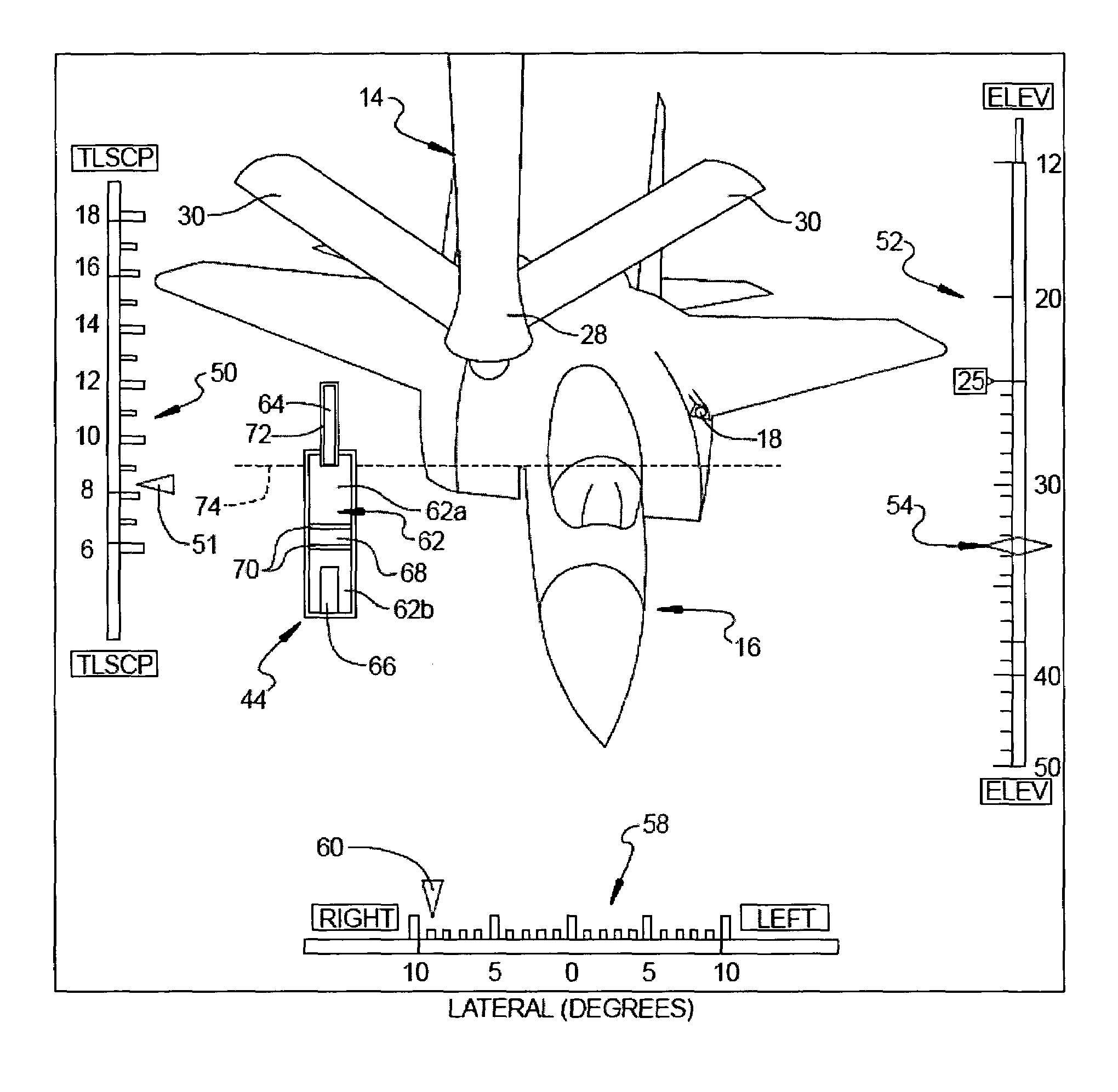
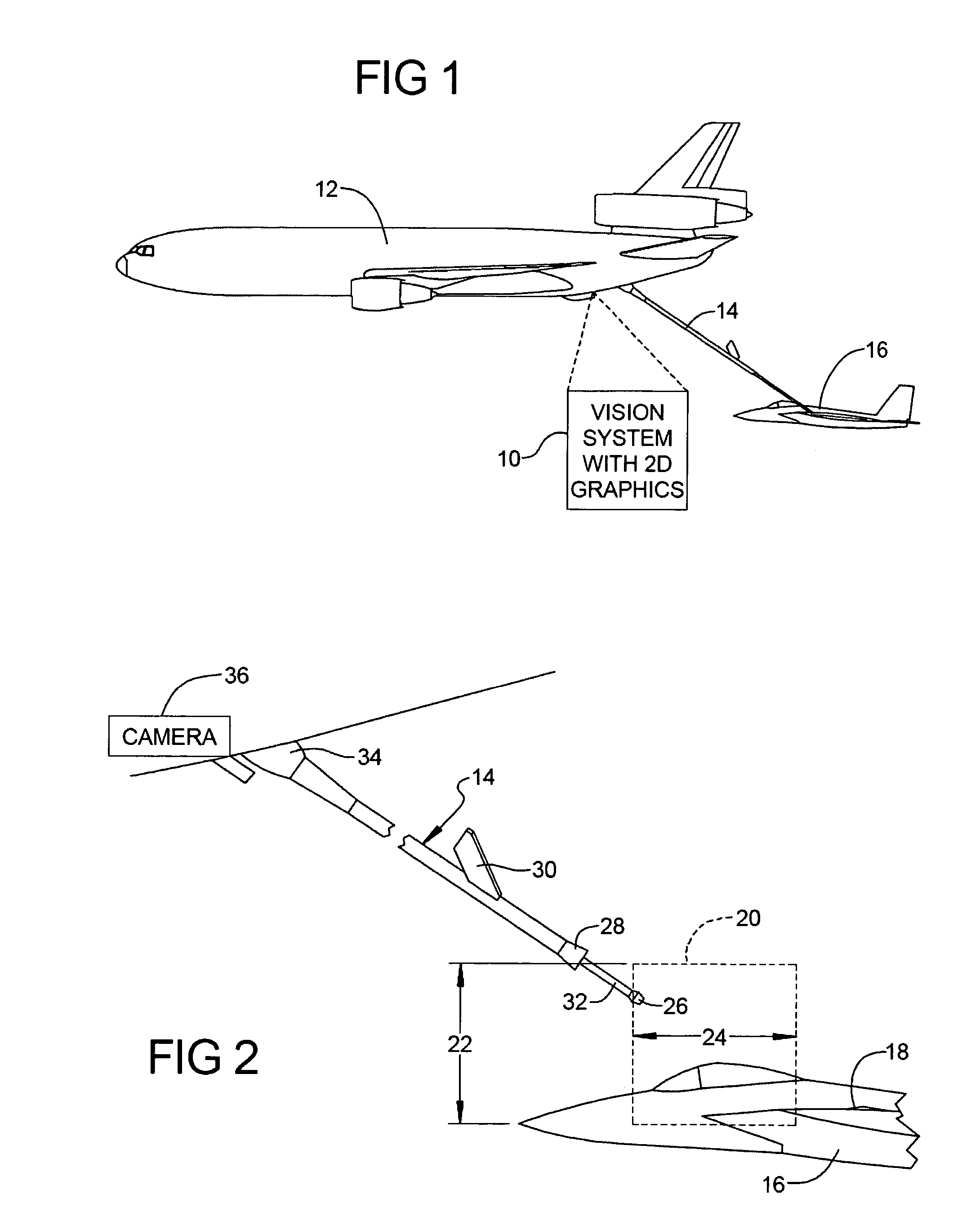
[0020]Referring to FIG. 1, a depiction of a refueling operation is illustrated. A tanker vehicle (i.e., aircraft) 12 carries a vision system 10 in accordance with a preferred embodiment of the present invention. The vision system 10 is used to enable the operator to control a telescoping refueling boom 14 to make contact with a refueling receptacle on a receiver vehicle (i.e., aircraft) 16.

[0021]Referring to FIG. 2, the receiver aircraft 16 and its associated refueling receptacle 18 can be seen relative to the boom 14. Dashed line 20 represents a “contact zone” having an elevation 22 and a distance 24 within which contact between a tip 26 of boom 14 needs to be made. The boom 14 can be seen to include a conventional ice shield 28 and a pair of conventional ruddervators 30 for assisting the boom operator in aiming the ...


PUM


Abstract

A vision system and method for use on a refueling tanker to assist a boom operator in performing an airborne refueling operation on a receiver aircraft. The system includes a digital camera system, a sensor subsystem and a processing system that receives information from the sensor system and the camera system. The processing system includes video processing capability and a graphics generator that generates a two dimensional graphics symbology set that is displayed on a display terminal along with a real time image of the boom and the receiver aircraft. The graphics symbology set includes a plurality of graphic symbols that indicate the position of the refueling boom and the position of the receiver aircraft relative to a desired contact zone within which physical contact between the boom tip and a refueling receptacle on the receiver aircraft can be made. The graphics symbology set also makes use of various colors to indicate warning conditions to the boom operator.

Description

CROSS-REFERENCE TO RELATED APPLICATIONS[0001]This application is related to concurrently filed application, U.S. Ser. No. 11 / 193,667, entitled “Graphical Symbology Apparatus For Use In An Airborne Refueling System” (Boeing reference no. 05-0659 VDD / HDP reference no. 7784-000869).FIELD OF THE INVENTION[0002]The present invention relates to refueling systems used in tanker aircraft for providing airborne refueling to a receiver aircraft, and more particularly to a vision system and method incorporating a two dimensional graphics symbology set for assisting a boom operator in aligning a refueling boom with a refueling receptacle on a receiver aircraft.BACKGROUND OF THE INVENTION[0003]Present tanker aircraft typically rely on three dimensional (3D) visual or stereo vision systems that are used by the boom operator to judge distance and closure rates between the receiver aircraft and the refueling boom and / or refueling hose / drogue. Creating an observation window for real vision or implem...

Claims


Application Information

Patent Timeline
Patent Type & Authority Patents(United States)
IPC IPC(8): B64D39/00
CPCB64D39/00
Inventor VON THAL, GERMANBENJAMIN, RONALD G
Owner THE BOEING CO
Why Eureka
Try Eureka