Modular drill

a module drill and drill bit technology, applied in the field of cutting tools, can solve the problems of reducing the service life of the shank, affecting the quality of the tool, and affecting the service life of the tool, so as to improve the service life and resist the distorting force. , the effect of eliminating sharp corners

Active Publication Date: 2007-12-18
KENNAMETAL INC
View PDF49 Cites 55 Cited by
  • Summary
  • Abstract
  • Description
  • Claims
  • Application Information

AI Technical Summary

Benefits of technology

[0003]The present invention provides modifications to drills having replaceable cutting tips, of the type shown in the above referenced patents to Hecht. The modifications of the present invention alter stresses imposed on the shanks such that the shanks either do not undergo deformation and outright failure while in service or alternatively, increase the service life achievable before deformation renders the tool unusable. These modifications generally connote prevention of direct contact of a replaceable cutting head with the shank at certain specified locations. Also, orientations of certain abutting surfaces are modified so that stresses are imposed differently from the original design of Hecht.
[0004]One specific example of modifications is that of providing a gap between a frustoconical dovetail formed in the cutting head and a cooperating recess formed in the shank, at the forward and rearward areas of mutual contact. The area of contact is limited to that portion between the forward and rearward areas of contact. A second modification is that of altering the angle of drive or torque transmission surfaces from purely radial to inclined relative to a purely radial direction. This has the effect of redistributing forces which would otherwise act on the walls of a pocket formed in the shank. The pocket, which receives the connection structure of the cutting head, then better resists distorting forces. A third modification is that of lengthening at the walls of that portion of the body forming a pocket which receives the cutting head and eliminating sharp corners in this region of the body. In still another modification, the floor of the pocket is modified in the manner of the third modification.
[0005]These modifications redistribute distorting forces away from portions of the shank which are more susceptible to distortion to portions of the shank better able to withstand these forces. The ultimate effect is to increase the useful service life of the shank due to reduced distortion of the pocket.

Problems solved by technology

While these devices will operate under some circumstances, closer analysis reveals that their useful lives are potentially unduly limited.
More specifically, the retaining and drive structure of the shank is subject to deformation and failure during its service life due to concentration of stresses imposed during ordinary service.

Method used


Image

  • Modular drill
  • Modular drill
  • Modular drill

Examples


Embodiment Construction

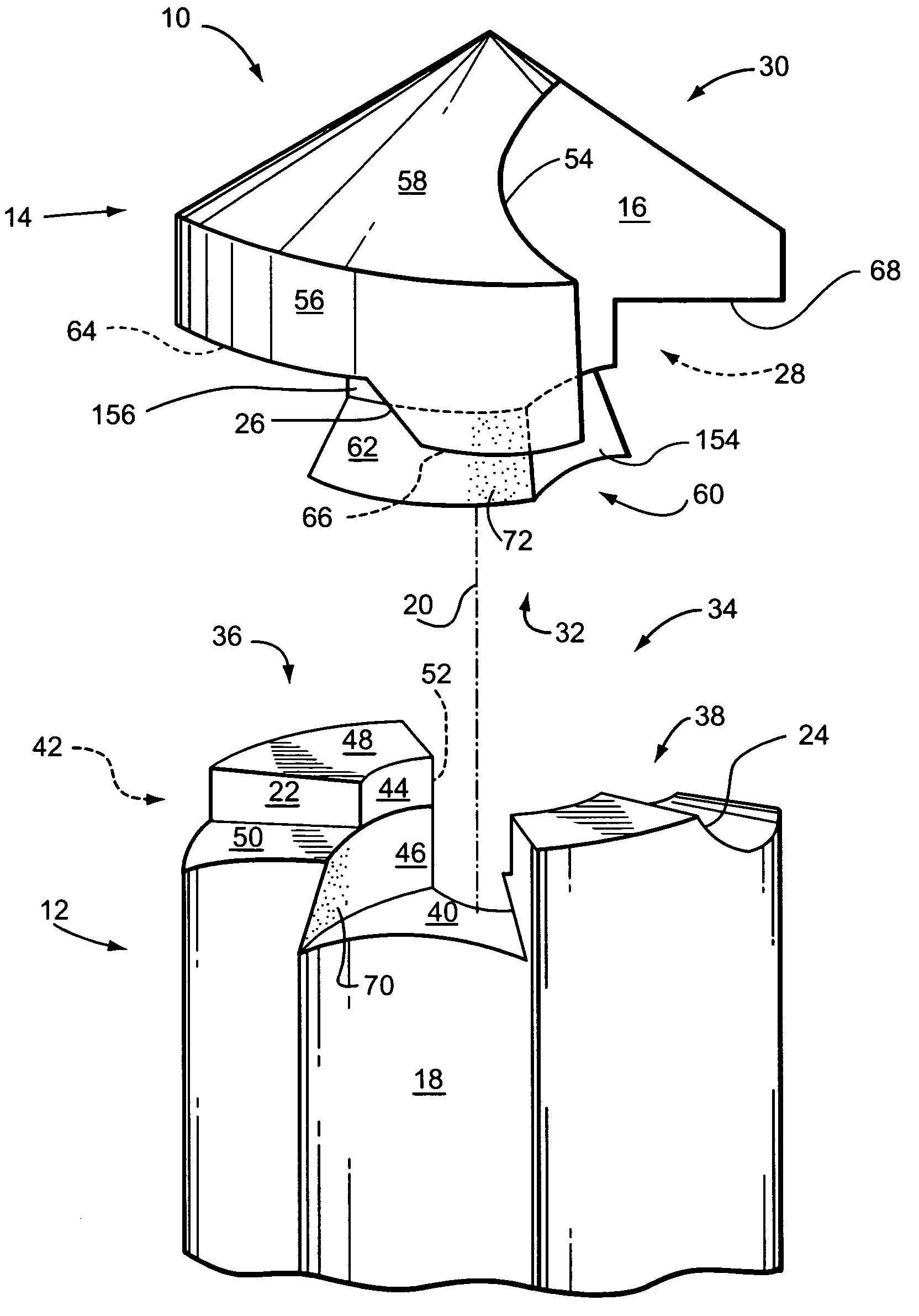
[0017]The documents, patents and patent applications referred to herein, including those pertaining to the prior art, are hereby incorporated by reference in their entirety. FIG. 1 of the drawings shows a first embodiment of a cutting tool assembly 10 for conducting rotary cutting operations on a work piece (not shown), comprising a tool shank 12 and a replaceable cutting head 14 which is installed on and engages tool shank 12. Cutting tool assembly 10 is a modular drill which in the preferred embodiments is of the so-called twist drill type, having helical flutes disposed along the sides of the drill. In the embodiment of FIG. 1, two flutes are provided in diametric opposition to one another, only one flute being visible. The visible flute has a lateral recess forming part of a flute, or cutting head flute portion 16 formed in cutting head 14. A corresponding or complementing lateral recess or shank flute portion 18 is formed in shank 12. The depiction of FIG. 1 shows cutting head ...


PUM

PropertyMeasurementUnit
stressaaaaaaaaaa
obtuse angleaaaaaaaaaa
forcesaaaaaaaaaa

Abstract

A drill having a replaceable cutting head, modified to eliminate forces which would distort the pocket of the drill shank and otherwise concentrate stresses which would cause failure of the drill. The cutting head has a frustoconical depending connecting member received in a receptacle formed in the shank. In different embodiments, contact between the pocket formed in the shank and the cutting head connecting member is limited. In one embodiment, angle of drive surfaces is modified from prior art practice. In another embodiment, transition of at curved joints between vertical and horizontal surfaces is made more gradual. The drill preferably has flutes formed collectively by the shank and cutting head when assembled.

Description

FIELD OF THE INVENTION[0001]The present invention relates to cutting tools, and more particularly to modular drills having replaceable cutting tips.DESCRIPTION OF THE RELATED ART[0002]Drills having replaceable cutting tips are known. Illustratively, such tools are shown in U.S. Pat. Nos. 5,957,631 and 6,059,492, both issued to Gil Hecht on Sep. 28, 1999, and May 9, 2000, respectively. The subject drills have replaceable cutting heads which are mounted on shanks. The cutting heads and shanks display continuous and complementing configuration as fluted drills. To this end, each shank has structure for retaining and rotating an associated cutting head. The associated cutting head has complementing structure for being retained and rotated by the shank. While these devices will operate under some circumstances, closer analysis reveals that their useful lives are potentially unduly limited. More specifically, the retaining and drive structure of the shank is subject to deformation and fai...

Claims


Application Information

Patent Timeline
Patent Type & Authority Patents(United States)
IPC IPC(8): B23B51/00
CPCB23B51/00B23B2251/02Y10T408/9097Y10T408/9098Y10T408/909
Inventor RUY FROTA DE SOUZA, FILHO
Owner KENNAMETAL INC
Why Eureka
Try Eureka