Coordinate input device

a technology of input device and input device, which is applied in the direction of input/output for user-computer interaction, instruments, computing, etc., can solve the problems of large device size, inability to perform desired input operation, and inability to slide the movable electrode b>56/b> properly, etc., to achieve small operation force, large sliding distance, and high operationability

Active Publication Date: 2007-12-18
ALPS ALPINE CO LTD
View PDF7 Cites 25 Cited by
  • Summary
  • Abstract
  • Description
  • Claims
  • Application Information

AI Technical Summary

Benefits of technology

[0037]Accordingly, it is an object of the present invention to solve the problems mentioned above by providing a compact, coordinate input device having high operationability, in which a coordinate input operation can be performed with a small operational force, and moreover, a large sliding distance is provided.

Problems solved by technology

Such a conventional coordinate input device, however, is problematic in that the device is large in size.
Otherwise, the movable electrode 56 cannot be slid properly.
Consequently, this may cause problems for, for example, women and children since they may not be able to slide the operating shaft 55 by a large distance and thus may not be able to perform a desired coordinate input operation.

Method used


Image

  • Coordinate input device
  • Coordinate input device
  • Coordinate input device

Examples


first embodiment

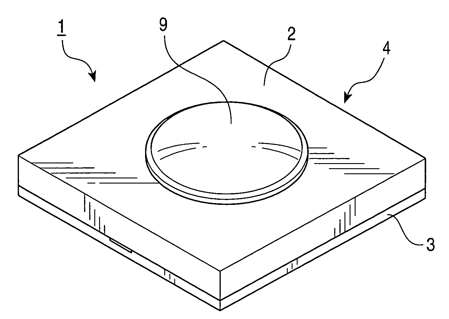
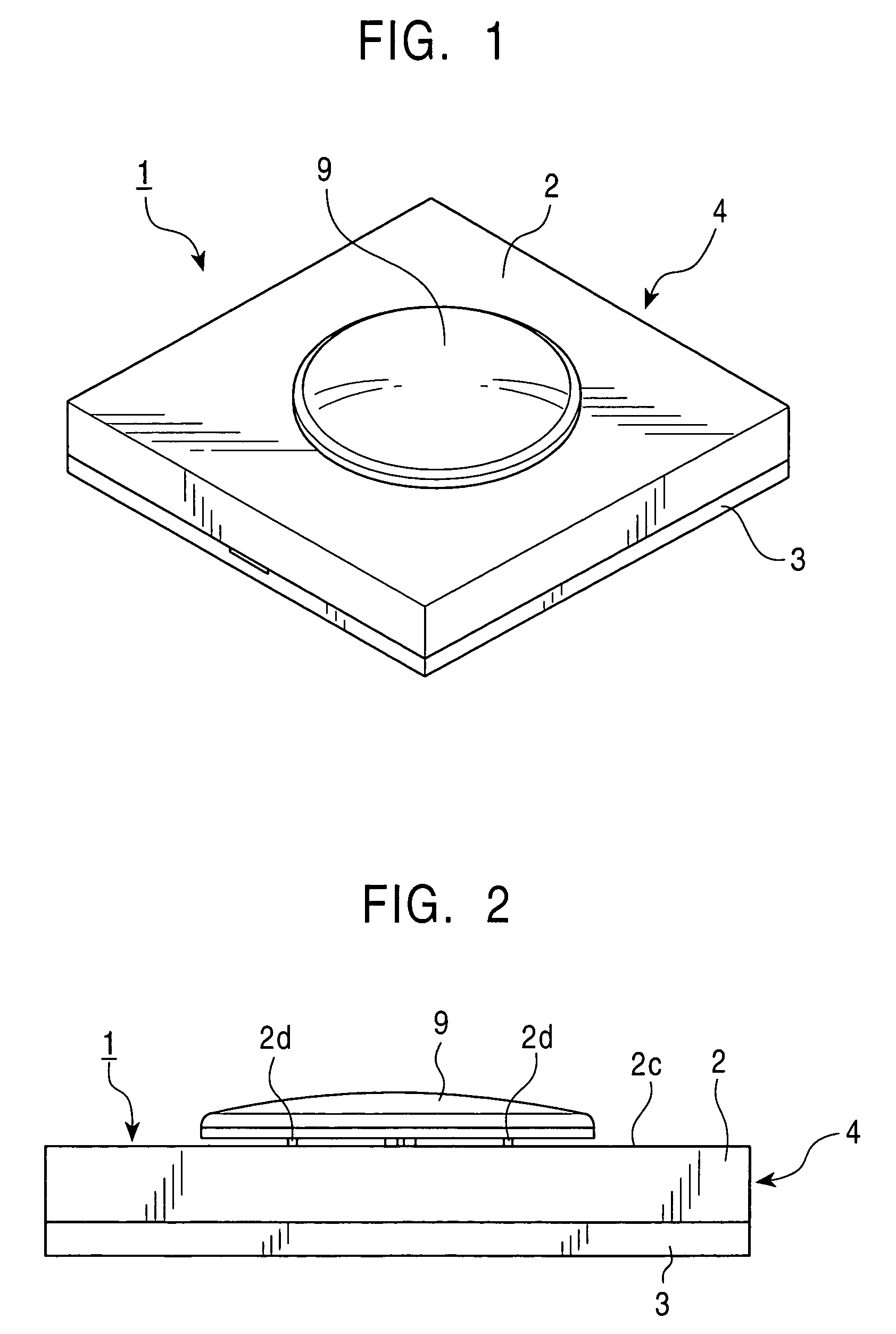
[0070]The coordinate input device 1 according to the first embodiment of the present invention will now be described with reference to FIGS. 1 to 8.

[0071]Referring to FIGS. 1 and 2, the coordinate input device 1 according to the first embodiment of the present invention is provided with a housing 4 whose profile is substantially rectangular. The housing 4 includes a first cover 2 and a second cover 3 which face each other.

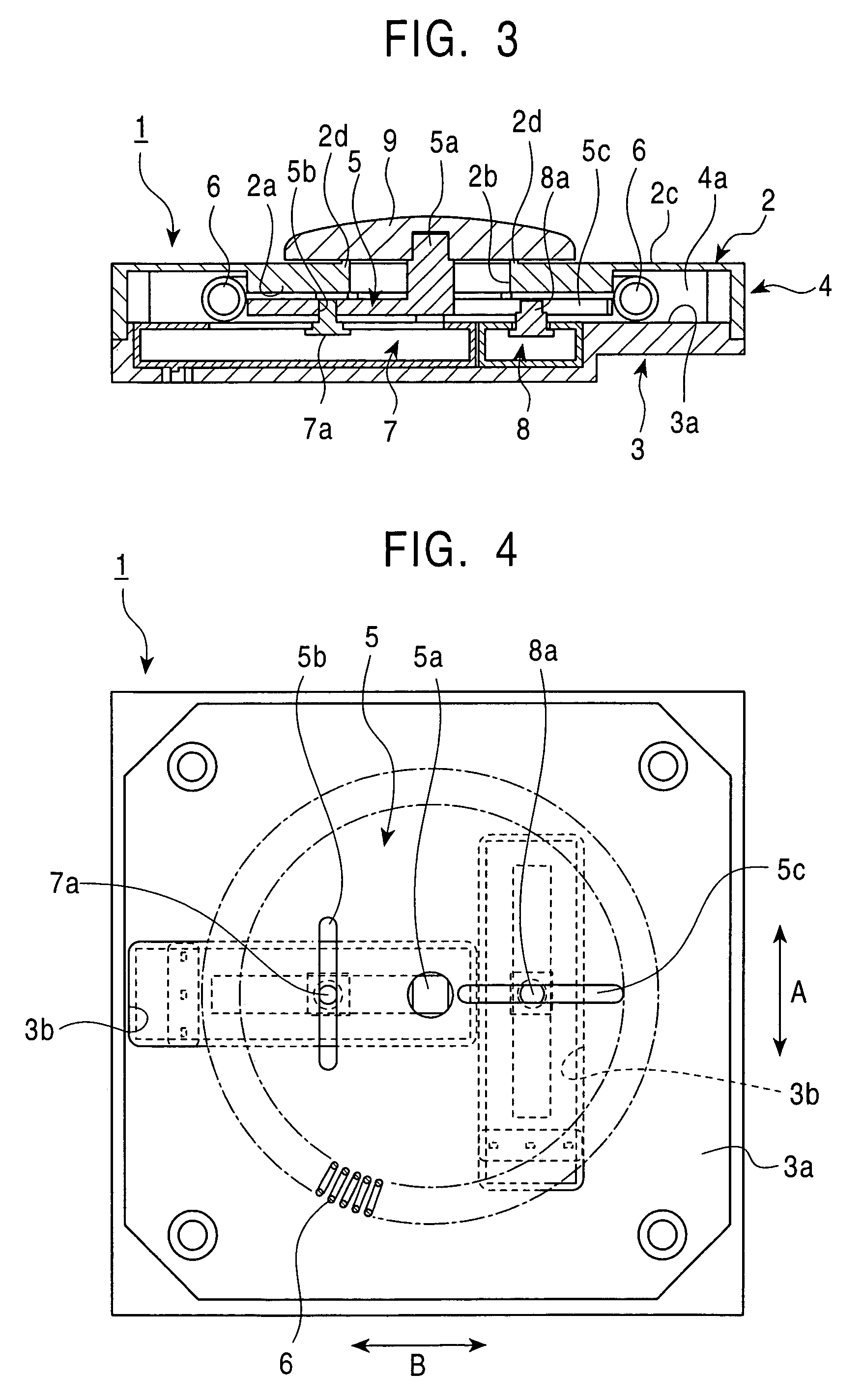
[0072]Referring to FIG. 3, the first cover 2 has a circular supporter 2a protruding downward towards the interior of the first cover 2 to a predetermined height. The central portion of the supporter 2a is provided with an opening 2b having predetermined dimensions. On the other hand, referring to FIG. 4, the second cover 3 has an inner surface 3a provided with a T-shaped recess 3b in which a first detector 7 and a second detector 8, which will be described later, are embedded.

[0073]Furthermore, referring to FIG. 3, the first cover 2 and the second cover 3 have a ca...

second embodiment

[0093]The coordinate input device 11 according to the second embodiment of the present invention will now be described with reference to FIGS. 7 and 8. Components equivalent to those in the first embodiment are indicated by the same reference numerals, and descriptions of those components will thus be omitted.

[0094]Referring to FIG. 7, the coordinate input device 11 of the second embodiment is provided with a housing 14 having a first cover 12 and a second cover 13 which face each other. The first cover 12 has a top plate 12a whose central portion is provided with an opening 12b having predetermined dimensions.

[0095]On the other hand, the second cover 13 has a circular supporter 13b protruding from the central portion of an inner surface 13a of the second cover 13 to a predetermined height. The supporter 13b supports the inner periphery of the resilient member 6.

[0096]Referring to FIGS. 7 and 8, the central portion of the supporter 13b is provided with a recess 13c in which the firs...

third embodiment

[0112]The coordinate input device 21 according to the third embodiment of the present invention will now be described with reference to FIGS. 11 and 12. Components equivalent to those in the first embodiment are indicated by the same reference numerals, and descriptions of those components will thus be omitted.

[0113]Referring to FIG. 11, the coordinate input device 21 of the third embodiment is provided with a housing 24 having a first cover 22 and a second cover 23 which face each other. The first cover 22 has a top plate 22a whose central portion is provided with an opening 22b having predetermined dimensions.

[0114]On the other hand, the central portion of an inner surface 23a of the second cover 23 is provided with a recess 23b which extends downward to a predetermined depth. The first cover 22 and the second cover 23 have a cavity 24a therebetween.

[0115]The cavity 24a contains a movable member 25 which is slidable in any direction while being in contact with the inner surface of...


PUM


Abstract

A coordinate input device includes a housing containing a movable member, a resilient member formed of a coil spring, and first and second detectors for detecting the sliding direction and the sliding distance of the movable member. The movable member in an initial position before a sliding operation faces a supporter of a first cover provided in the housing. When the movable member is slid in a certain direction, the resilient member is stretched in the certain direction and the first and second detectors detect the sliding direction and the sliding distance of the movable member. When the sliding operation of the movable member is finished, a resilient force of the resilient member stretched in the certain direction forces the movable member to return automatically to the initial position.

Description

[0001]This application claims the benefit of priority to Japanese Patent Application No. 2003-202501, herein incorporated by reference.BACKGROUND OF THE INVENTION[0002]1. Field of the Invention[0003]The present invention relates to coordinate input devices, and particularly, to a coordinate input device which allows desired input by sliding an operating part and which is suitable for, for example, personal computers, mobile phones, and video game units.[0004]2. Description of the Related Art[0005]FIGS. 13 and 14 illustrate a conventional coordinate input device which can be operated by sliding an operating part to perform a desired input operation. Such a conventional coordinate input device is disclosed in Japanese Unexamined Patent Application Publication No. 2003-84916. The coordinate input device includes an upper casing 51 at the top portion of the device, and an insulative lower casing 52 which faces the upper casing 51 and is disposed below the upper casing 51.[0006]The upper...

Claims


Application Information

Patent Timeline
Patent Type & Authority Patents(United States)
IPC IPC(8): G09G5/00G06F3/0354
CPCG06F3/03548
Inventor HAGIWARA, YASUJISOMA, MASAHIROTAKATA, MASAHIRO
Owner ALPS ALPINE CO LTD
Why Eureka
Try Eureka