
Multilayer shim peeling device

a multi-layer, peeling device technology, applied in metal working equipment, chemistry apparatus and processes, manufacturing tools, etc., can solve the problems of shims that are not usable, shims that are bent out of shape, and provide no means to adjust the height of the wafer in relation to the height of the wafer

Inactive Publication Date: 2008-01-01
NORTHROP GRUMMAN SYST CORP
View PDF7 Cites 13 Cited by
  • Summary
  • Abstract
  • Description
  • Claims
  • Application Information

AI Technical Summary

Benefits of technology

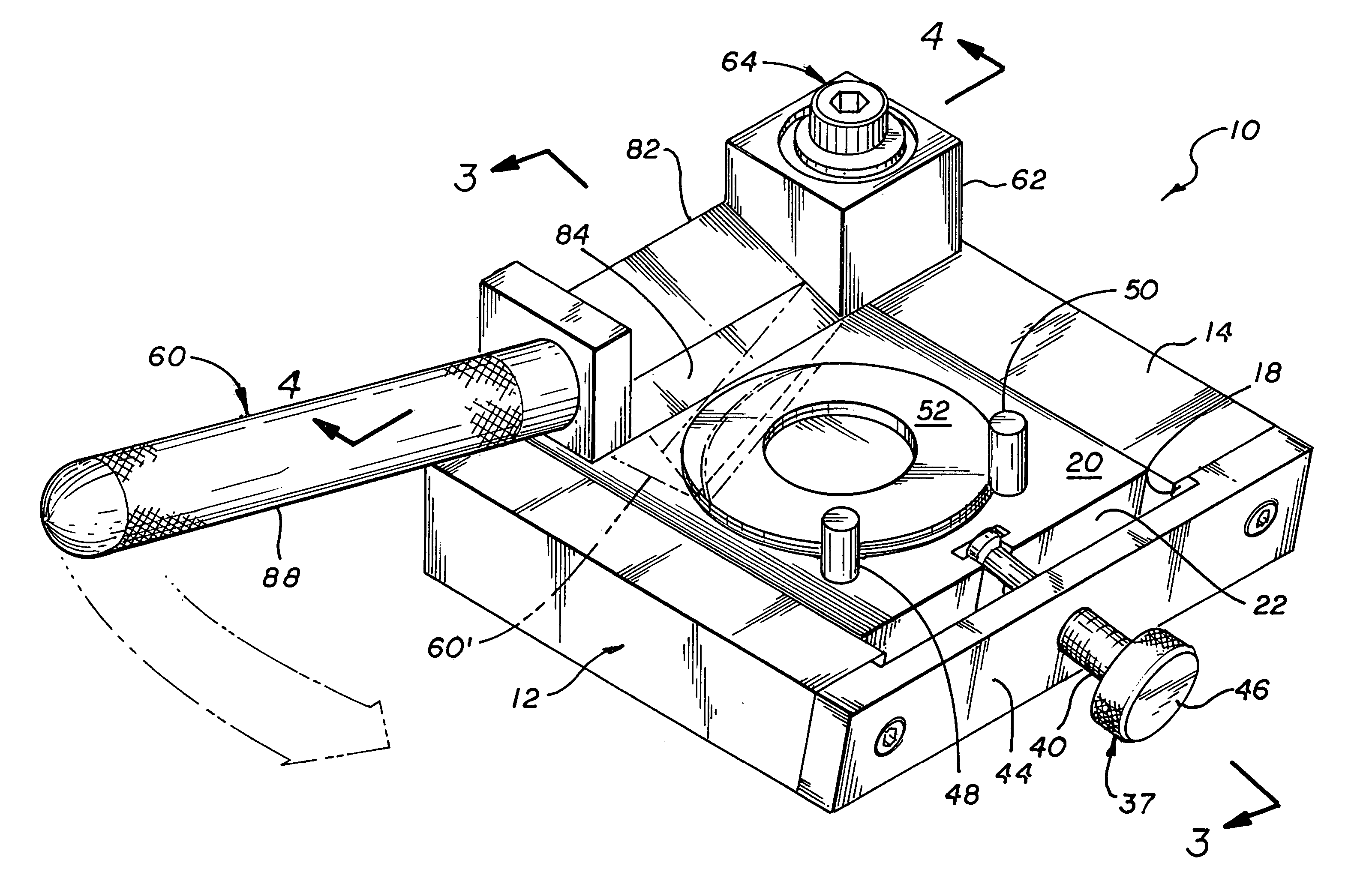
The invention is a device for peeling off layers of a multilayer shim. The device includes a platform with a recess and a mechanism for mounting and moving the shim upward. The mechanism includes a first block with a tapered surface and a second block with a tapered lower surface in contact with the first block. The second block can have a third block with a tapered surface that can hold the shim. The device also includes a blade assembly that can be rotated to peel off the shim. The technical effect of the invention is to provide a simple and efficient device for peeling off layers of a multilayer shim.

Problems solved by technology

However with large shims, the use of a knife without proper support can cause the laminated shim to be bent out of shape.
Quite often, too many layers were removed making the shim unusable.
However, this device provides no means to adjust the height of the wafer in relationship to the spatula.
Thus it could not be used to remove variable number of layers from a laminated shim by peeling.
This device could not be used with a multilayer shim because the individual layers are so thin that they would bundle up and rip apart leaving portions still laminated in place.
In addition, there is no means to vary the number of layers of shim to be removed.

Method used


Image

  • Multilayer shim peeling device
  • Multilayer shim peeling device
  • Multilayer shim peeling device

Examples


Embodiment Construction

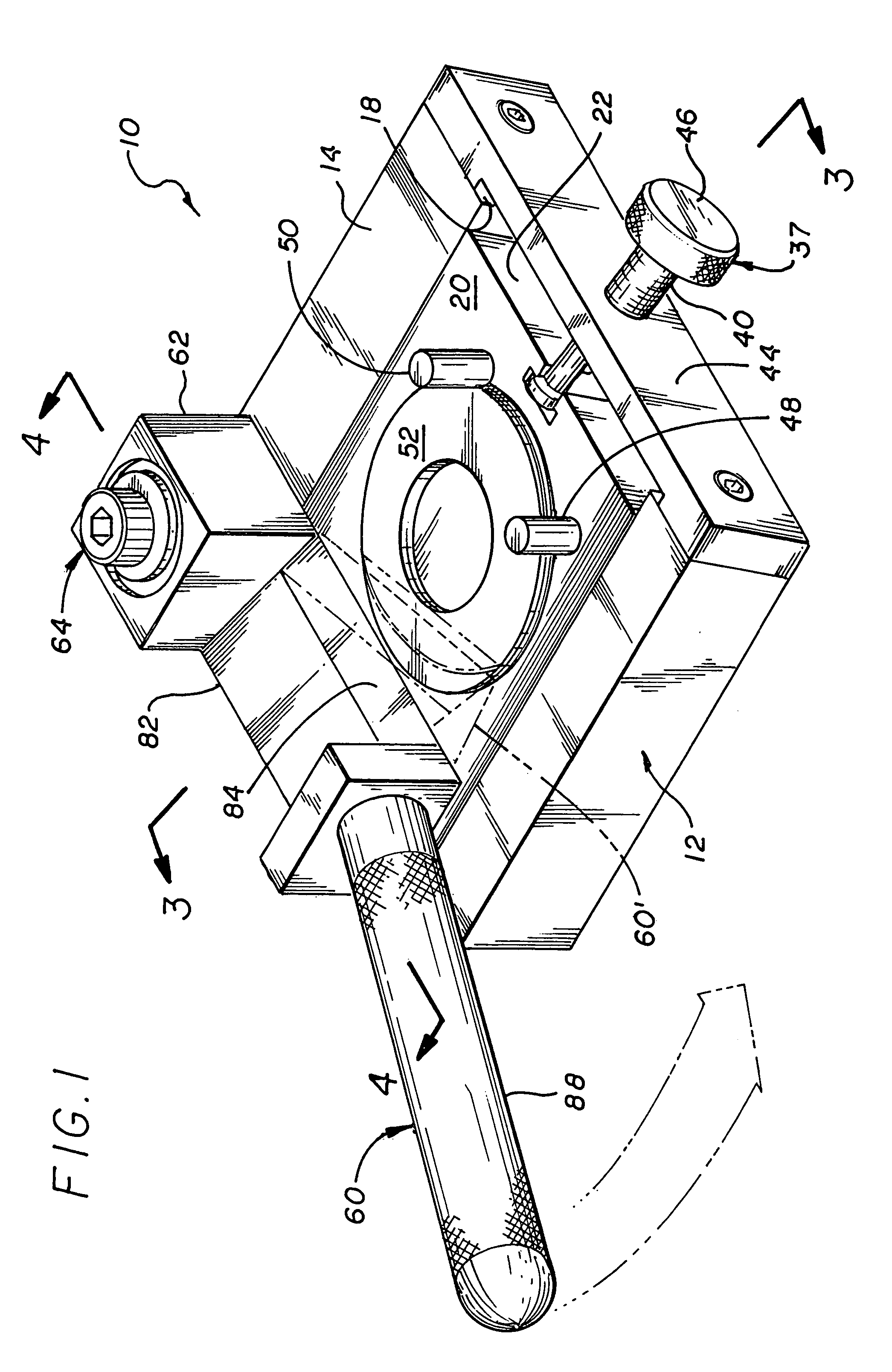
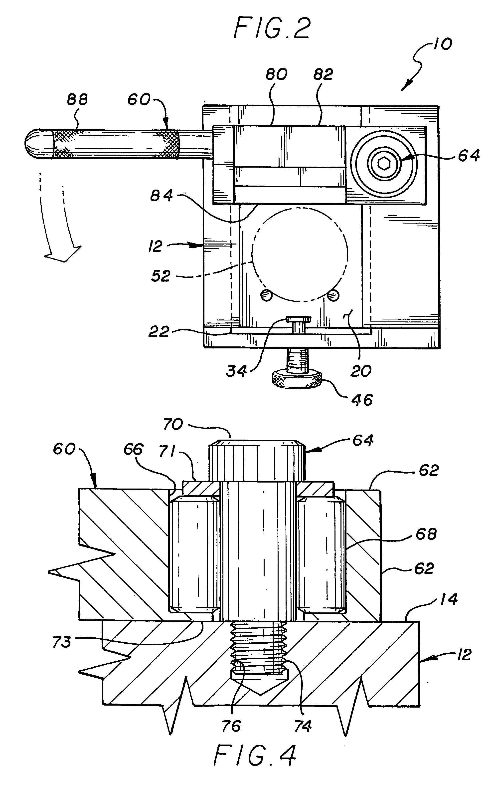
[0020]Referring to FIGS. 1-4, the device, generally indicated by numeral 10, includes a platform assembly 12, having a flat upper surface 14 with a square recess 16, with the recess having a flat bottom surface 18. A wedge assembly 20 is mounted in the recess providing a gap 22. The wedge assembly 20 comprises a upper and lower tapered blocks 24 and 26 with mating tapered surfaces 28 and 30 in slidable contact with each other and with the top surface 30 of block 24 and bottom surface 32 of block 26 parallel to each other. The taper angle 33 is approximately 10 degrees. The bottom block 26 is fixed to the bottom surface 18 of the recess 16 by either bonding or fasteners (not shown). Of course, the bottom block could be integral with the platform assembly 16. The upper block 24 includes a T shaped notch 34 at end 36. A bolt 37 having a T shaped end 38 in engagement with the T shaped notch 34 and a threaded mid portion 40 that threadably engages a threaded hole 42 in the wall 44 and te...


PUM

PropertyMeasurementUnit
taper angleaaaaaaaaaa
angleaaaaaaaaaa
thicknessaaaaaaaaaa

Abstract

The invention is a device for peeling one or more individual layers of a multilayer shim. In detail the device includes a platform having a surface with a recess. A mechanism is mounted in the recess for mounting the shim and a moving the shim upward such that a portion of the shim is above the surface. A blade assembly is rotatably mounted to the platform, which is rotatable in a plane parallel to the surface. The blade assembly includes a cutting blade mounted thereon, such that said blade is in slidable contact with the surface and movable over the recess. Thus shim can be raised by the mechanism and the portion of the shim requiring removal can be raised above the surface and the blade assembly thereafter can be rotated causing the cutting blade to shear off the portion of the shim above the surface.

Description

BACKGROUND OF THE INVENTION[0001]1. Field of the Invention[0002]The invention relates to the field of metal removal tools and, in particular, to a device to peel off layers of a laminated multilayer shim.[0003]2. Description of Related Art[0004]Multilayer laminated shims are used in a wide variety of applications to eliminate unwanted movement between joined parts do to tolerance discrepancies. Their primary advantage is that shims of different thickness' need not be shocked. Furthermore, the time consuming task of assembling a multiple number of shims of different thickness is no longer required. One need only measure the gab that needs to be filled, and thereafter peel off the layers of the laminated shim tell the proper thickness is obtained. This was typically accomplished by prying each layer off with a sharp edged knife or the like. However with large shims, the use of a knife without proper support can cause the laminated shim to be bent out of shape. Quite often, too many la...

Claims


Application Information

Patent Timeline
Patent Type & Authority Patents(United States)
IPC IPC(8): B32B38/10B26D1/26B26D7/06
CPCB32B43/006Y10T156/1184Y10T156/1967B32B2311/00Y10T83/05Y10T83/6499Y10T83/6508
Inventor WARDELL, JOSEPH P.WANG, TIENCHENG
Owner NORTHROP GRUMMAN SYST CORP
Learn More