Slam latch for rackmount rail

a technology for latching racks and racks, applied in the direction of hinge/pivot support structures, light support devices, building scaffolds, etc., can solve the problems of frequent drop and loss of screws, user discomfort, and dangerous work environmen

Active Publication Date: 2008-01-15
ORACLE INT CORP
View PDF32 Cites 121 Cited by
  • Summary
  • Abstract
  • Description
  • Claims
  • Application Information

AI Technical Summary

Benefits of technology

[0011]In an embodiment, an outer slide assembly may include a slam latch for coupling an outer slide member with the rack. The slam latch may automatically close when the slam latch is placed on a rack rail. An engaging member of the slam latch may engage a portion of the rack rail to couple the slam latch with the rack rail. The engaging member may maintain the outer slide assembly at a desired height with respect to the rack rail.

Problems solved by technology

To install the screws, users may be forced to maintain uncomfortable positions in cramped quarters for extended periods of time.
Generally, a user must ensure that the slide assemblies are level front-to-back, which may be made difficult due to space limitations and a lack of easily read position markers.
Screws are frequently dropped and lost during the installation process.
Leaving the screws loose may create a dangerous work environment, as the relatively heavy equipment is under-supported during installation.
In addition, users may forget to tighten the screws after the component is installed.
In some cases, there are “extra” holes in the component chassis, so that the desired mounting location is not clear to the user.
Many components for servers are heavy, and installation of such components is often a two-person job.
Because the equipment is heavy and often must be installed at an awkward height, this installation step sometimes results in damage to the slides (and to the equipment if dropped).
Also, in some cases, the fixturing method used to secure the equipment in place is not robust enough to withstand large magnitude shock or vibration loads (e.g., as may be experienced in earthquakes).

Method used


Image

  • Slam latch for rackmount rail
  • Slam latch for rackmount rail
  • Slam latch for rackmount rail

Examples


Embodiment Construction

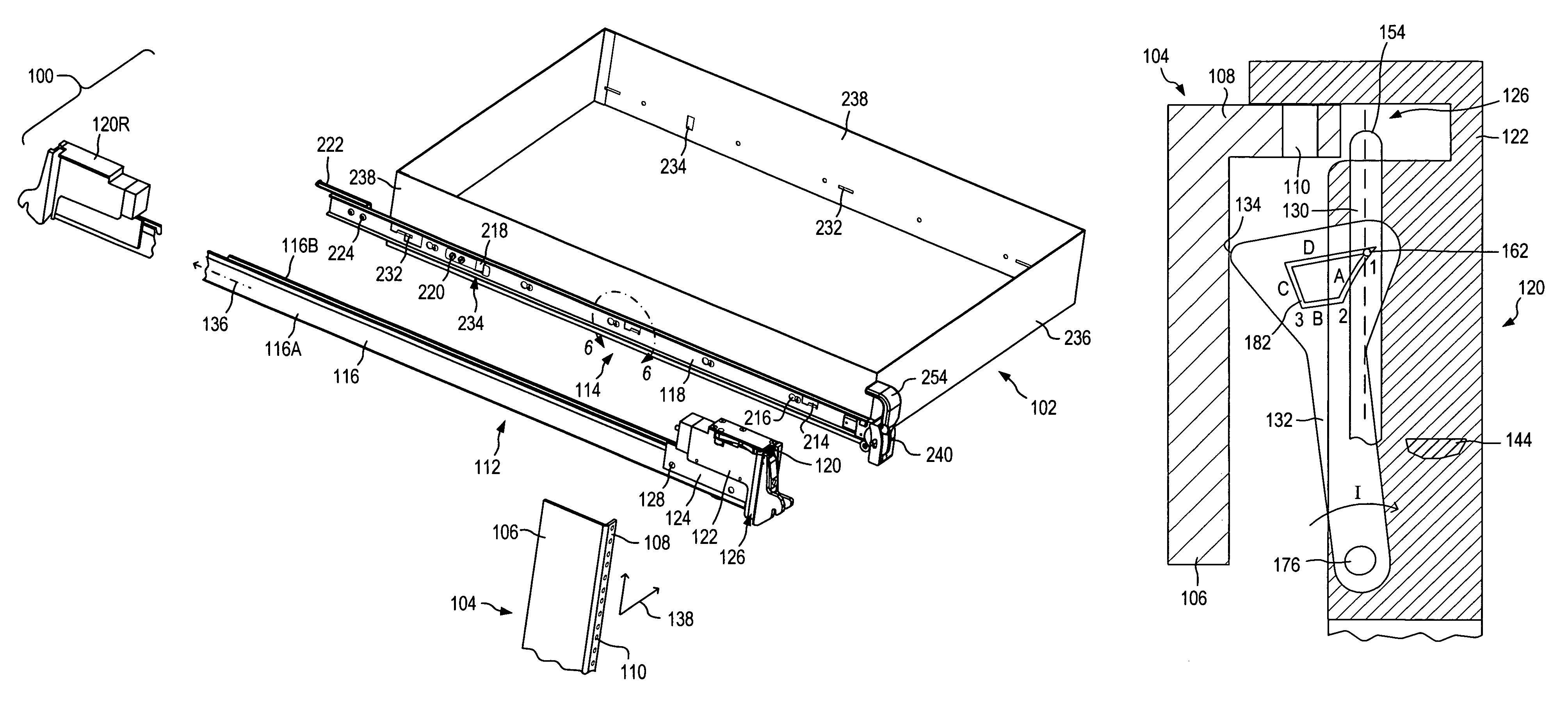
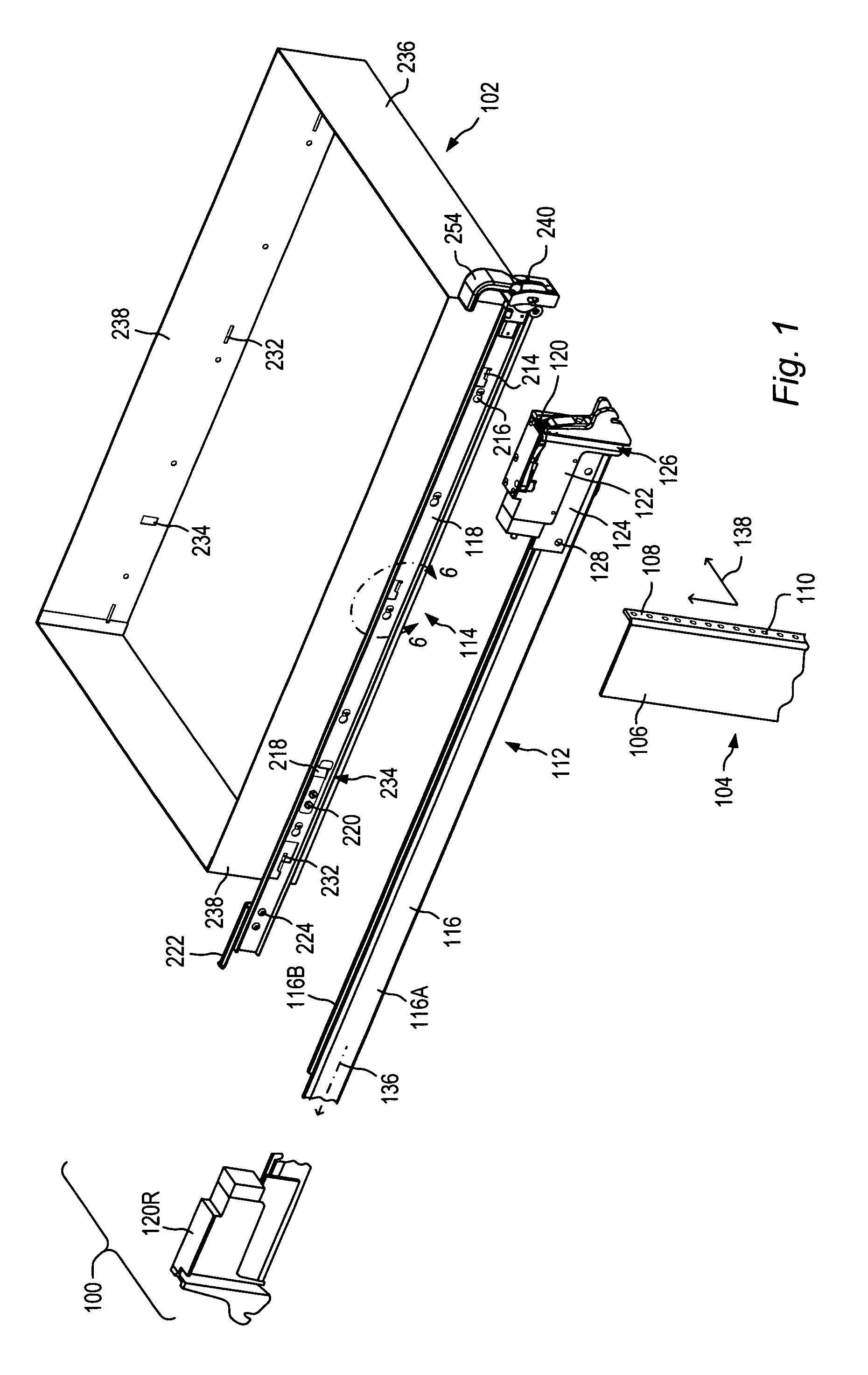
[0034]A system for mounting a component in a rack may include slide assemblies. Each slide assembly may include an outer slide member to be attached to the rack and a complementary inner slide member to be attached to the component. In some embodiments, the slide members may allow for attachment to the component and the rack without the use of any tools. For example, an outer slide assembly may include a latch that engages a portion of a rack rail to secure an outer slide member to the rack rail. An inner slide member may include tabs. The tabs may engage slots in a chassis of a component to secure the inner slide member to the component.

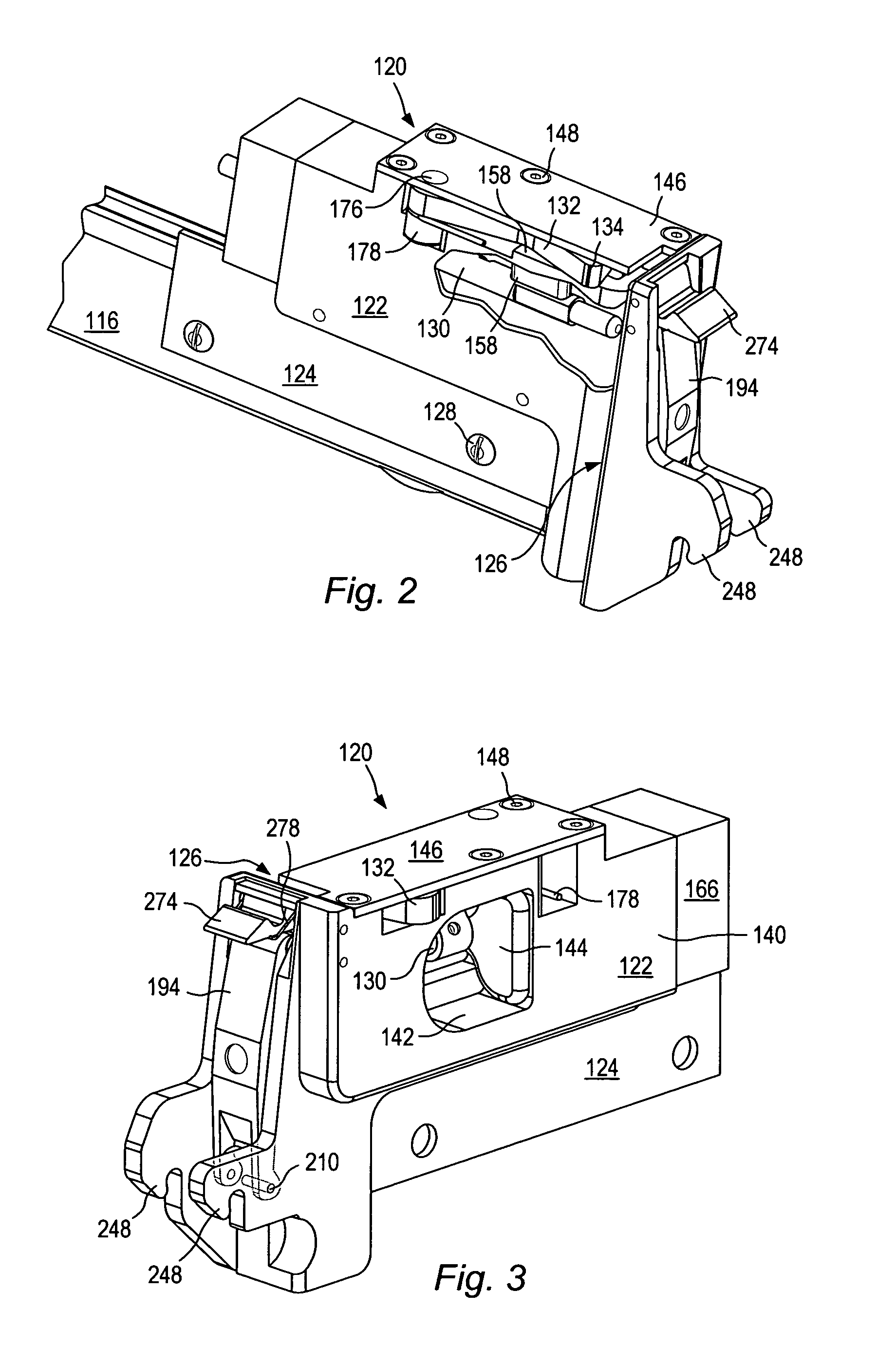
[0035]In some embodiments, a slide assembly may include a latch. A latch on a slide assembly may advantageously eliminate a need for a tool to install the slide assembly in a rack. A latch on a slide assembly may also eliminate a need for separate fasteners (e.g., screws) to install the slide assembly. Eliminating separate fasteners may reduce the n...


PUM


Abstract

A rackmount system for a component may include outer slide members that couple with inner slide members. The outer slide members may be coupled to a rack with slam latches. The slam latches may couple with rails of the rack when the slam latches are placed against the rails. The inner slide members may be coupled to a component. The inner slide members may include tabs that engage slots in a chassis of the component to couple the inner slide members to the component. An inner slide assembly may include an inner latch that couples with the outer slide member to inhibit movement of the inner slide member relative to the outer slide member. The rackmount system may include a locking mechanism that locks the component relative to the rack.

Description

BACKGROUND OF THE INVENTION[0001]1. Field of the Invention[0002]This invention relates generally to electronic equipment, such as computers, and, more particularly, to apparatus for mounting electronic equipment in racks.[0003]2. Background Information[0004]Electronic systems such as computers are typically constructed in a modular fashion. Large systems such as servers may include multiple components installed in a rack. As used herein, “component” includes any of various elements or systems of equipment, including, but not limited to, circuit cards, disk drives, or power supplies. Electronic elements of a component are commonly housed in chassis or other enclosures. As used herein, “rack” or “rack assembly” includes any assembly or structure adapted to receive or house a component.[0005]Components may be installed in racks using slide assemblies. Typically, a pair of outer slides is installed on vertical rails on the interior sides of the rack, and a pair of complementary inner sl...

Claims


Application Information

Patent Timeline
Patent Type & Authority Patents(United States)
IPC IPC(8): H05K5/00A47F7/00H05K7/14
CPCH05K7/1405Y10T403/60Y10T403/7088
Inventor LEE, DANIEL Z.BRIGHAM, ARTHUR S.JONES, III, WILLIAM R.JENSEN, JOEL F.SILVERMAN, DENISE R.FRANK, CHRISTOPHER H.AQUINO, SARAHMORI, ROBERT F.
Owner ORACLE INT CORP
Why Eureka
Try Eureka