Biofidelic shoulder brace

a biofidelic, shoulder brace technology, applied in the field of orthopaedic braces, can solve the problems of affecting athletic performance, affecting athletic performance, and limiting the first category of braces, so as to achieve greater or less pressur

Inactive Publication Date: 2008-01-22
BECKER ORTHOPEDIC APPLIANCE CO +1
View PDF32 Cites 20 Cited by
  • Summary
  • Abstract
  • Description
  • Claims
  • Application Information

AI Technical Summary

Problems solved by technology

The shoulder allows more range of motion than any other joint in the body, and for that reason, it is more susceptible to injury than other joints.
Generally speaking, the first category of braces—those that restrict motion—may be too limiting for certain types of athletic activities.
Many of the braces that fall into the second and third categories (i.e., those that apply direct and indirect forces to the shoulder) can hamper athletic function by interfering with respiration, scapulothoracic motion, or muscular excursion.
This is important because anterior shoulder instability most commonly develops when the restraints of the humeral head are inadequate or excessive force is being applied, usually when the shoulder is in abduction, extension or external rotation.
By preventing or limiting those positions, however, athletes who suffer these types of injuries or weaknesses would be particularly impaired in their ability to perform their respective activities.

Method used


Image

  • Biofidelic shoulder brace
  • Biofidelic shoulder brace
  • Biofidelic shoulder brace

Examples


Embodiment Construction

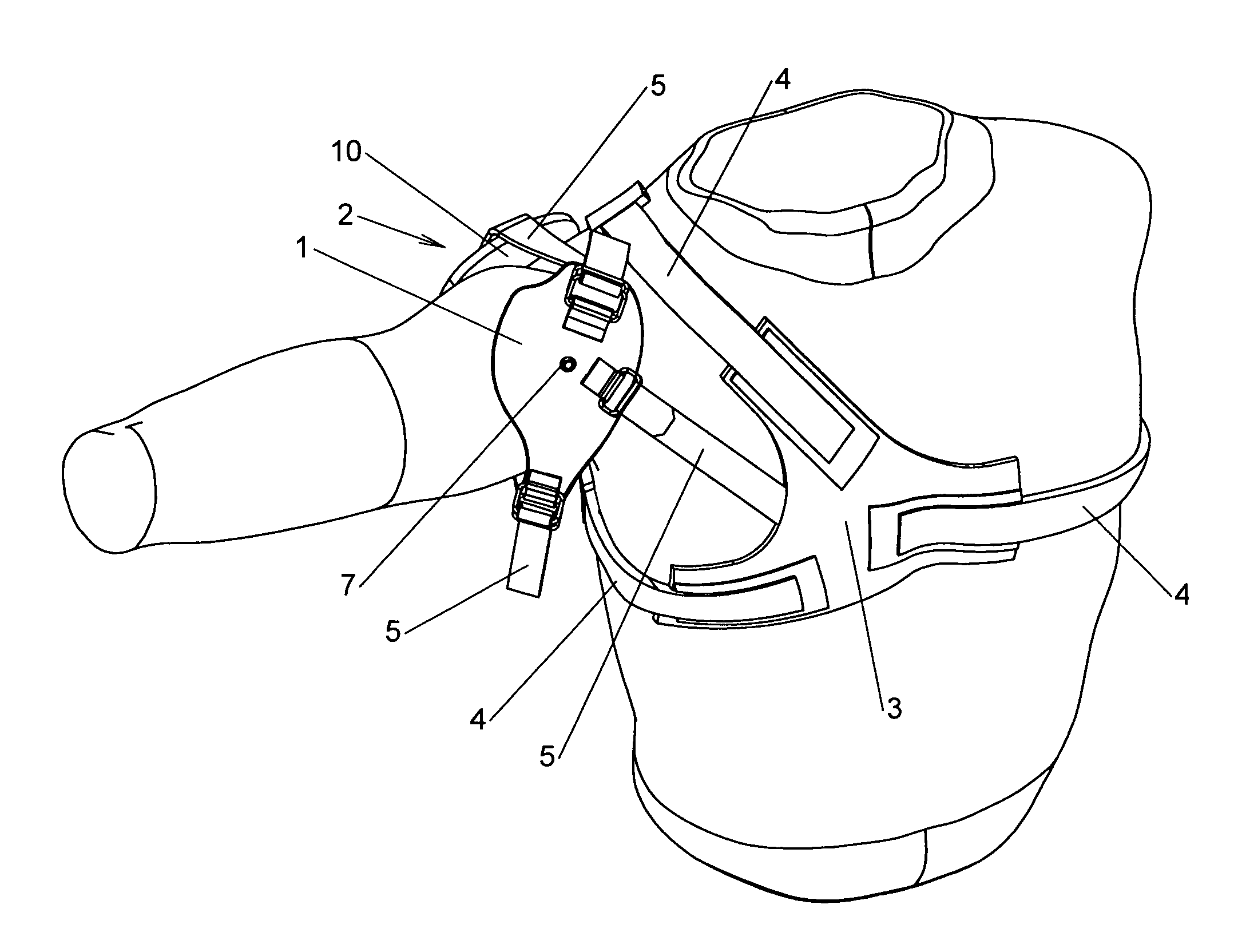
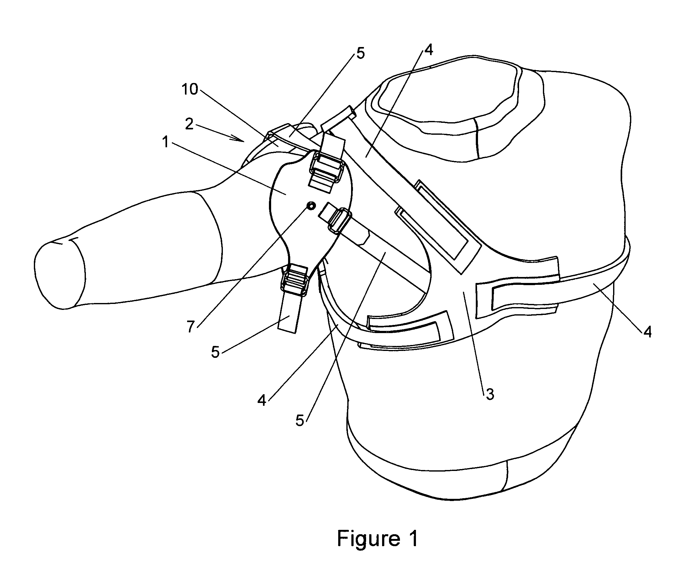
[0063]FIG. 1 is a front perspective view of the shoulder brace of the present invention on the wearer. The shoulder brace of the present invention comprises six main elements. These elements are the anterior shoulder support member 1, the posterior support member 2, the strap attachment member 3, three primary straps 4, three secondary straps 5, and a pneumatic pad 6 (not shown). The pneumatic pad 6 lies on the inner surface of the anterior shoulder support member 1 and is inflatable through an inflation nipple 7 that extends from the pneumatic pad 6 through the anterior shoulder support member 1 and is visible on the front of the brace. The pneumatic pad can be inflated or deflated by a small air pump (see FIGS. 9 and 10) or similar mechanism that can be attached to the air nipple.

[0064]The anterior shoulder support member 1 is roughly oval and slightly concave, and it is positioned directly over the humeral head of the shoulder so that it forms a slight cup over the humeral head. ...


PUM


Abstract

A shoulder brace comprising an anterior shoulder support member, a posterior support member, a strap attachment member, three primary straps, three secondary straps, and a pneumatic pad. The posterior support member comprises a back support member and a scapular support member. The back support member preferably comprises a lateral extension, an upper extension and a lower extension. The primary straps are preferably elastic and are used to don the brace. The secondary straps are preferably flexible but not elastic and are used to adjust the position of the anterior shoulder support member over the humeral head of the wearer.

Description

BACKGROUND OF THE INVENTION[0001]1. Field of the Invention[0002]The present invention relates to the field of orthopedic braces, and more particularly, to a shoulder brace with a pneumatic pad for increasing or decreasing pressure against the humeral head of the shoulder.[0003]2. Description of the Related Art[0004]The shoulder allows more range of motion than any other joint in the body, and for that reason, it is more susceptible to injury than other joints. Anterior shoulder instability resulting from an initial shoulder disclocation is the primary complaint. In fact, ninety-five percent (95%) of shoulder injuries relate to anterior shoulder instability. Various types of shoulder braces have been developed to prevent or minimize anterior shoulder instability. These braces generally fall into three categories: those that limit the shoulder to a “safe zone” by restricting excessive abduction, extension and external rotation; those that apply a direct force to the shoulder; and thos...

Claims


Application Information

Patent Timeline
Patent Type & Authority Patents(United States)
IPC IPC(8): A61F5/00
CPCA61F5/3723
Inventor CAMPBELL, JAMES H.BROICK, RODGER D.KANIA, BRUCE G.ZIMMERMAN, DAVID L.HARDING, WARREN
Owner BECKER ORTHOPEDIC APPLIANCE CO
Why Eureka
Try Eureka